Talus fusion surface type artificial ankle joint prosthesis

An ankle, surface-type technology, used in ankle joints, prostheses, joint implants, etc., can solve the problem of difficult to achieve effective fusion of autologous bone and metal prosthesis, and achieve the effect of improving the fusion rate

Pending Publication Date: 2021-12-17
PEOPLES HOSPITAL PEKING UNIV
View PDF0 Cites 0 Cited by
  • Summary
  • Abstract
  • Description
  • Claims
  • Application Information

AI Technical Summary

Problems solved by technology

But its disadvantages are also obvious, that is, it is difficult to achieve effective fusion between autogenous bone and metal prosthesis

Method used


Image

  • Talus fusion surface type artificial ankle joint prosthesis
  • Talus fusion surface type artificial ankle joint prosthesis

Examples


Embodiment 1

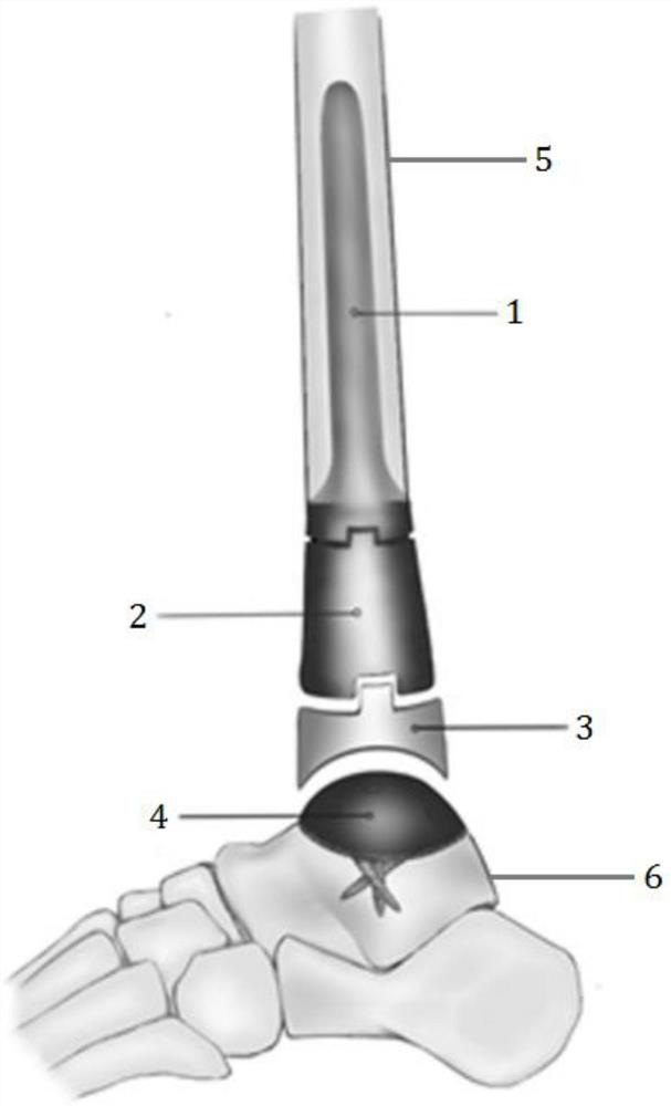
[0029] figure 1 A tumor-type talus fusion surface-type artificial ankle joint prosthesis is shown, which is mainly suitable for reconstruction of bone defects in limbs with interrupted continuity after distal tibial tumor resection. The tumor-type talus fusion surface-type artificial ankle joint prosthesis includes: tibial bone marrow The prosthetic stem 1 is fixed in the tibial medullary cavity, and the upper end of the prosthetic stem 1 fixed in the tibial medullary cavity is used for fastening connection with the tibial medullary cavity 5; the prosthesis segment 2 is conically connected to the lower end of the prosthetic stem 1 fixed in the tibial medullary cavity ; the joint liner 3 is embedded in the lower end of the prosthesis segment 2, and the lower surface of the joint liner 3 is a concave arc surface structure; the talar surface prosthesis 4, the lower part of the talus surface prosthesis 4 is tightly connected with the talus 6, The upper surface of the talar surface...

Embodiment 2

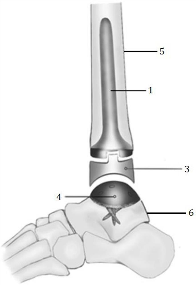
[0036] figure 2 A surface-replacement talar fusion surface-type artificial ankle prosthesis is shown, which is mainly suitable for ankle joint injuries, rheumatoid arthritis and other cases. The surface-replacement talar fusion surface-type artificial ankle joint prosthesis includes: tibial medullary cavity The internal fixation prosthesis handle 1, the upper end of the fixed prosthesis handle 1 in the tibial medullary cavity is used for fastening connection with the tibial medullary cavity 5; The lower surface of the liner 3 is a concave arc surface structure; the talar surface prosthesis 4, the lower part of the talar bone surface prosthesis 4 is tightly connected with the talus 6, and the upper surface of the talar bone surface prosthesis 4 is a polished convex arc surface structure and is connected to the joint lining. The lower surface of the pad 3 is conformally matched to form a smooth motion joint, so that the plantar flexion and dorsiflexion functions of the tibiotal...


PUM

PropertyMeasurementUnit
sizeaaaaaaaaaa
porosityaaaaaaaaaa

Abstract

The invention relates to a talus fusion surface type artificial ankle joint prosthesis. The artificial ankle joint prosthesis comprises a tibia bone marrow cavity internal fixing prosthesis handle, a prosthesis segment, a joint pad and a talus surface prosthesis, wherein the upper end of the tibia bone marrow cavity internal fixing prosthesis handle is connected with the tibia bone marrow cavity in a fastened mode; the prosthesis segment is conically connected to the lower end of the tibia bone marrow cavity internal fixing prosthesis handle; the joint pad is inlaid in the lower end of the prosthesis segment, and the lower surface of the joint pad is of a concave cambered surface structure; and the lower portion of the talus surface prosthesis is connected with the talus in a fastened mode, and the upper surface of the talus surface prosthesis is of a polished convex cambered surface structure and is matched with the lower surface of the joint pad in a conformal mode to form a smooth movement joint. The artificial ankle joint prosthesis can be widely applied to bone defect reconstruction of limb continuous interruption after tibia far-end tumor excision, the aim of limb structure recovery can be achieved, meanwhile, perfect combination of immediate stability and long-term stability of the tibial astragaloid joint is achieved, and therefore the long-term ankle joint function of a patient is remarkably improved.

Description

technical field [0001] The invention relates to an artificial prosthesis, in particular to a talus fusion surface-type artificial ankle joint prosthesis based on 3D printing technology, which belongs to the technical field of medical devices. Background technique [0002] The tibia is the second most common site of osteosarcoma next to the femur. The tibial osteosarcoma accounts for about 19% of the total body osteosarcoma, and 20% of the tibial osteosarcoma occurs in the distal tibia. Due to the many tendons, blood vessels and nerves in the distal tibia, it is difficult to obtain a good tumor margin. Therefore, some scholars recommend below-knee amputation as the preferred surgical method for distal tibial osteosarcoma. However, with the advancement of chemotherapy and surgical techniques, limb salvage treatment for distal tibial osteosarcoma can also achieve good survival rates, and is recognized and recommended by the majority of bone tumor doctors. [0003] There are v...

Claims


Application Information

Patent Timeline
Patent Type & Authority Applications(China)
IPC IPC(8): A61F2/42A61F2/30
CPCA61F2/4202A61F2/30771A61F2/30942A61F2002/30329A61F2002/30784A61F2002/30985A61F2002/4205A61F2002/4207
Inventor 郭卫
Owner PEOPLES HOSPITAL PEKING UNIV
Why Eureka
Try Eureka