Safe and energy-saving flat heat pipe air-cooled fuel cell stack and heat management method

A technology of fuel cell stacks and flat heat pipes, applied in fuel cells, secondary batteries, circuits, etc., can solve problems such as high parasitic power and uneven battery temperature, reduce internal resistance, reduce volumetric power density, and save size Effect

Pending Publication Date: 2021-12-21
赵耀华
View PDF8 Cites 0 Cited by
  • Summary
  • Abstract
  • Description
  • Claims
  • Application Information

AI Technical Summary

Problems solved by technology

[0011] Aiming at the problems of uneven battery internal temperature and large parasitic power existing in the existing low-power air-cooled fuel cell

Method used


Image

  • Safe and energy-saving flat heat pipe air-cooled fuel cell stack and heat management method
  • Safe and energy-saving flat heat pipe air-cooled fuel cell stack and heat management method
  • Safe and energy-saving flat heat pipe air-cooled fuel cell stack and heat management method

Examples


Embodiment 1

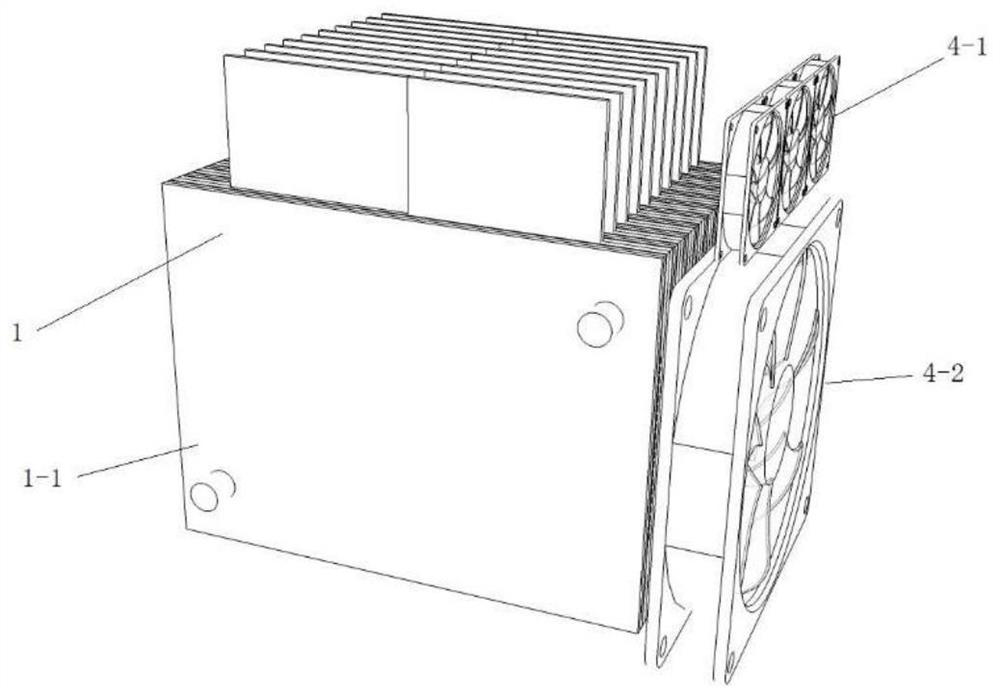
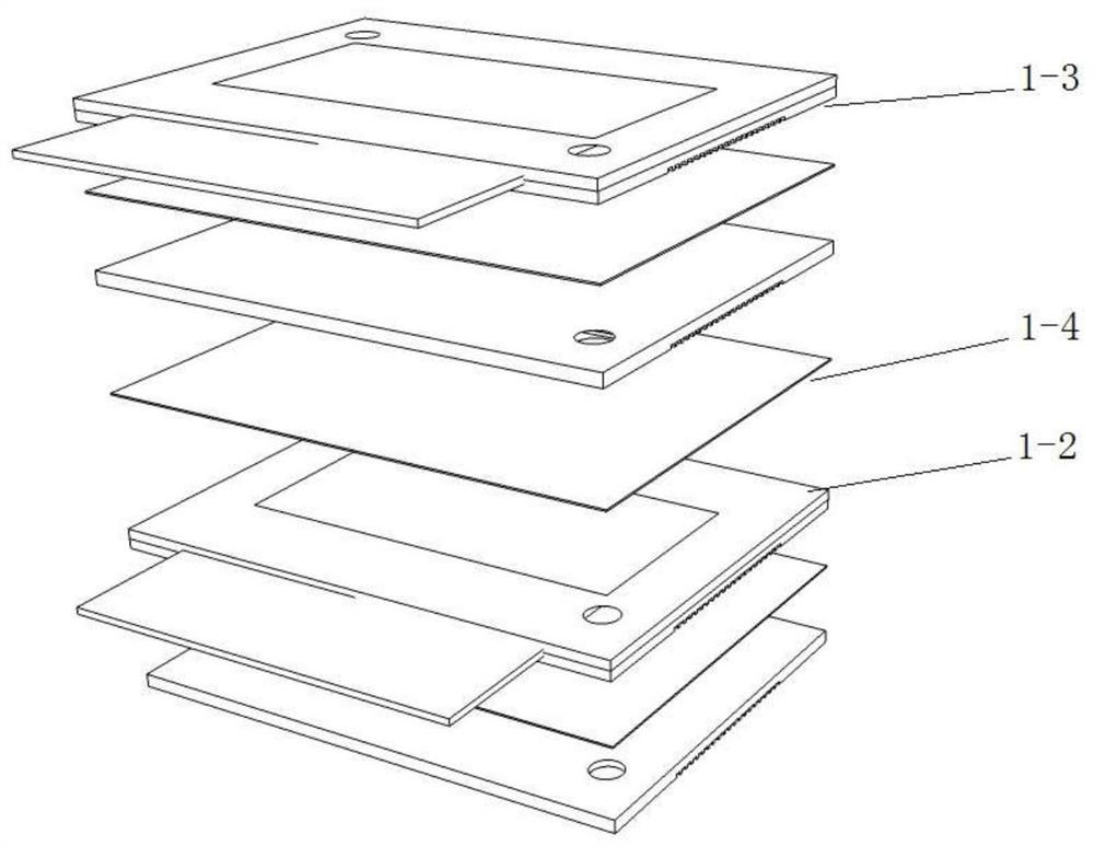
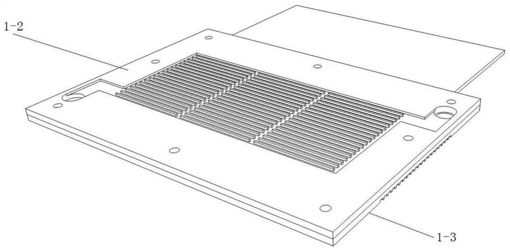
[0032] Such as Figure 1-3 As shown, this implementation case is a safe and energy-saving flat-plate micro-heat pipe air-cooled fuel cell stack, which is composed of a fuel cell stack 1 , a micro-heat pipe array 2 and a fan 4 . The fuel cell stack 1 includes two end plates 1-1, a current collector, multiple membrane electrodes 1-4 and multiple sets of bipolar plates, and the multiple membrane electrodes 1-4 and bipolar plates are arranged alternately. Part of the bipolar plate is attached to the micro heat pipe array 2 to form a bipolar plate with the micro heat pipe array, and part of the bipolar plate is not attached to the heat pipe and formed into a single plate. The bipolar plate with the micro heat pipe array 2 is composed of a plurality of anode plates 1-2 and cathode plates 1-3 attached to the micro heat pipe array 2 in the middle, and the micro heat pipe array 2 is attached to the anode plate 1-2 and the cathode plate 1 -3 in the middle, and closely arranged together...

Embodiment 2

[0035] In this embodiment, a fuel cell stack using air-cooled micro heat pipe arrays for thermal management, on the basis of Embodiment 1, additional fins 3 are added.

[0036] Such as Figure 4 As shown, in order to increase the heat exchange area, the protruding part of each of the micro heat pipe arrays 2 is attached to the upper fin 3 with thermal silica gel, and the heat is transferred from the fin 3 through the work of the cooling fan 4-1 installed above the fin 3 The inside of the battery is taken away, which has the effect of cooling the fuel cell.

Embodiment 3

[0038] In this embodiment, a fuel cell stack using air-cooled micro heat pipe arrays for thermal management, on the basis of the structure of embodiment 1 or embodiment 2, the micro heat pipe array 2 not only includes the inline micro heat pipe array 2, but also includes An L-shaped micro heat pipe array 2, and an electric heating chip 5 is arranged on the L-shaped micro heat pipe array 2.

[0039] Such as Figure 5 As shown, several groups of bipolar plates are spaced apart, and an L-shaped micro heat pipe array 2 is attached between the anode plate 1-2 and the cathode plate 1-3, or part of the inline micro heat pipe array 2 is replaced by an L-shaped micro heat pipe array2. The electric heating sheet 5 is attached to the bent portion of the end of the L-shaped micro heat pipe array 2 .

[0040] A fuel cell stack that utilizes micro heat pipe array air-cooling for heat management, using the above heat management system, a micro heat pipe array 2 is attached between the anod...


PUM

PropertyMeasurementUnit
Hydraulic diameteraaaaaaaaaa

Abstract

The invention discloses a safe and energy-saving flat heat pipe air-cooled fuel cell stack and a heat management method.The flat heat pipe air-cooled fuel cell stack is formed by combining two end plates, a collector plate, a plurality of membrane electrodes and a plurality of sets of bipolar plates, wherein the membrane electrodes and the bipolar plates are alternately arranged between the two end plates; parts or all of the bipolar plates are attached to a micro heat pipe array, the micro heat pipe array can transfer heat generated when hydrogen makes contact with air through the proton exchange membrane to a condensation section of the micro heat pipe array, and natural convection heat dissipation or forced convection heat dissipation is conducted through an external fan. According to the invention, heat dissipation of the fuel cell can be realized, the temperature uniformity in the stack is increased, and the reliability is improved.

Description

technical field [0001] The invention relates to the technical field of hydrogen energy technology fuel cell heat management, in particular to a safe and energy-saving flat heat pipe air-cooled fuel cell stack and a heat management method. Background technique [0002] Due to the increasing demand for energy, the consumption of fossil fuels and the CO 2 The total emissions are rising rapidly, and the "clean, low-carbon, safe, and efficient" energy revolution is the general trend. Hydrogen energy is a clean secondary energy carrier that can be easily converted into electricity and heat with high conversion efficiency and has multiple sources. As a bridge connecting renewable energy and traditional fossil energy, it is an important part of the future energy transformation. [0003] Hydrogen fuel cells have the advantages of high fuel energy conversion rate, low noise and zero emissions, and can be widely used in automobiles, airplanes, trains and other vehicles as well as sta...

Claims


Application Information

Patent Timeline
IPC IPC(8): H01M8/2465H01M10/617H01M10/6551H01M10/6563
CPCH01M8/2465H01M10/6551H01M10/6563H01M10/617Y02E60/10Y02E60/50
Inventor 赵耀华王林成徐红霞全贞花
Owner 赵耀华
Why Eureka
Try Eureka