Waste gas spray tower with tail gas purification treatment

A tail gas purification and treatment tower technology, applied in the field of spray towers, can solve the problems of lack of tail gas purification structure, lack of waste water treatment structure, lack of particulate matter detection structure, etc.

Inactive Publication Date: 2021-12-24
江苏科闻环保科技有限公司
View PDF10 Cites 3 Cited by
  • Summary
  • Abstract
  • Description
  • Claims
  • Application Information

AI Technical Summary

Problems solved by technology

[0008] The object of the present invention is to provide a waste gas spray tower with tail gas purification treatment to solve the problems of lack of tail gas purification structure, lack of flow velocity detection structure, lack of particulate matter detection structure and lack of waste water treatment structure proposed in the above background technology

Method used


Image

  • Waste gas spray tower with tail gas purification treatment
  • Waste gas spray tower with tail gas purification treatment
  • Waste gas spray tower with tail gas purification treatment

Examples


Embodiment 2

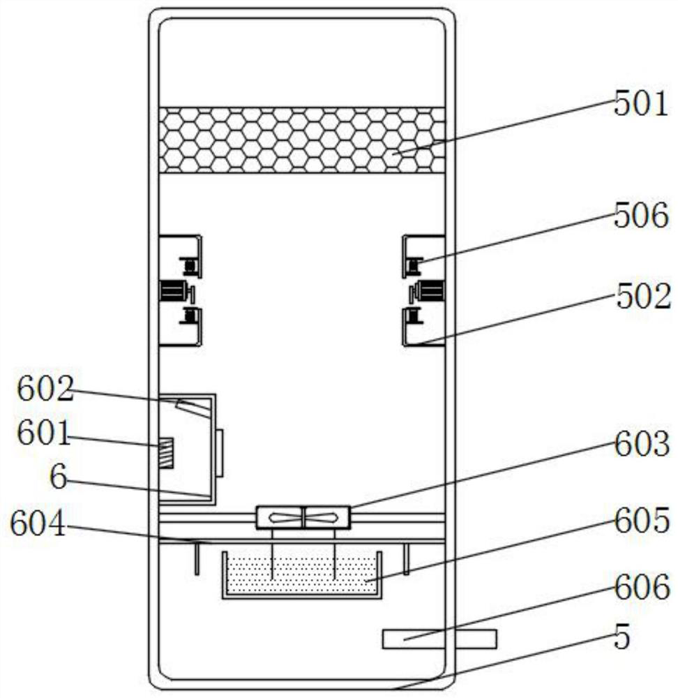
[0042] Example 2: see image 3 and Figure 4 , an embodiment provided by the present invention: a waste gas spray tower with tail gas purification treatment, the inner wall of the purification tower 5 is equipped with an activated carbon net 501, and the inner wall of the purification tower 5 is equipped with an igniter 502, and the igniter 502 is located on the activated carbon Below the net 501, a motor 503 is installed on the inner wall of the igniter 502, a cam 504 is installed on the output end of the motor 503, a fixed plate 505 is installed on the inner wall of the igniter 502, and a No. 1 spring 506 is installed on the bottom of the fixed plate 505. A flint 507 is installed at the bottom of the 506, a signal receiver 601 is installed on the inner wall of the protective case 6, an inclined laser transmitter 602 is installed on the inner wall of the protective case 6, a sealing plate is installed on the inner wall of the purification tower 5, and the top of the sealing p...

Embodiment 3

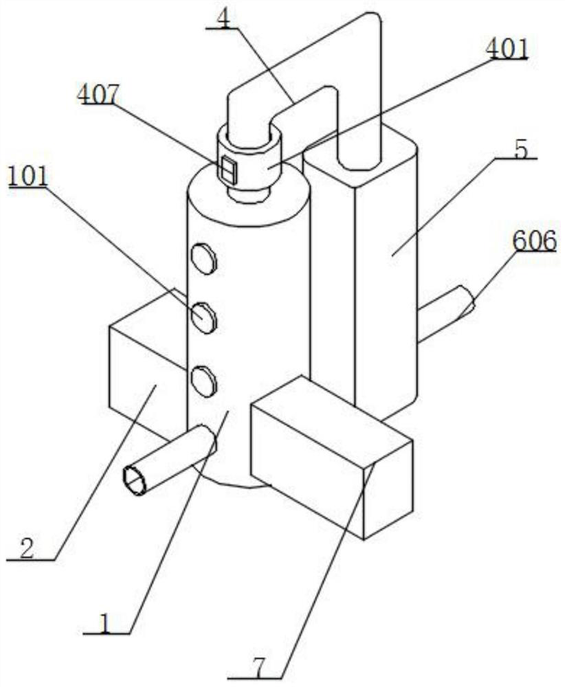
[0043] Example 3: See Figure 8 , an embodiment provided by the present invention: a waste gas spray tower with tail gas purification treatment, a flow detector 401 is installed on the outer wall of the connecting pipe 4, a rotating rod 402 is installed through the inner wall of the connecting pipe 4, and the rotating rod 402 Blades 403 are installed around the outer wall of the rotating rod 402, a reflector 404 is installed on the outer wall of the rotating rod 402, a support plate is installed on the inner wall of the flow detector 401, a processor 405 is installed on the top of the support plate, and an infrared signal transmitter is installed on the inner wall of the processor 405. An infrared signal receiver is installed on the inner wall of the processor 405, and the infrared signal receiver is located on one side of the infrared signal transmitter. The purified exhaust gas passes through the connecting pipe 4, and then the flow detector 401 detects the flow rate of the e...

Embodiment 4

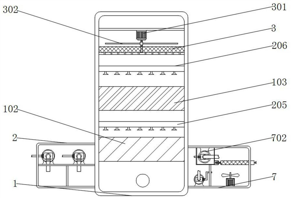
[0044] Example 4: See figure 1 , figure 2 and Figure 5 , an embodiment provided by the present invention: a waste gas spray tower with tail gas purification treatment, No. 1 purification block 102 is installed on the inner wall of the treatment tower 1, No. 2 purification block 103 is installed on the inner wall of the treatment tower 1, and the second The No. 1 purification block 103 is located above the No. 1 purification block 102. A plurality of portholes 101 are installed on the outer wall of the treatment tower 1. A No. 2 box 201 is installed on the inner bottom wall of the feed box 2. A No. 1 water pump 202 is installed on the top of the No. 1 box 201. , the input end of the No. 1 water pump 202 extends into the inside of the No. 1 box 201, the output end of the No. 1 water pump 202 extends into the inside of the treatment tower 1, and the output end of the No. 1 water pump 202 is equipped with a spray pipe 205, and the feed box 2 No. 2 tank 203 is installed on the ...


PUM


Abstract

The invention discloses a waste gas spray tower with tail gas purification treatment, the waste gas spray tower comprises a treatment tower, a feeding box, a connecting pipe, a purification tower and a wastewater tank, the top of the treatment tower is provided with the connecting pipe, one end of the connecting pipe is provided with the purification tower, the outer wall of one side of the treatment tower is provided with the feeding box, the waste water tank is mounted on the outer wall of the other side of the treatment tower, absorbent cotton is mounted on the inner wall of the treatment tower, a protective shell is mounted on the inner wall of the purification tower, and a purification groove is formed in the bottom wall in the waste water tank. Waste gas can be completely purified by installing a plurality of water pumps and spraying pipes, the waste gas moves upwards to meet the first purification block, the first water pump drives purification liquid in the first box to be sprayed out from the first spraying pipe, and the waste gas passing through the first purification block is purified for the first time; a second water pump pumps the liquid medicine in the second box to a second spraying pipe, and then the liquid medicine is sprayed out of the second spraying pipe, so that the waste gas is purified for the second time, and the function of purifying the waste gas is achieved.

Description

technical field [0001] The invention relates to the technical field of spray towers, in particular to an exhaust gas spray tower with exhaust gas purification treatment. Background technique [0002] The spray tower exists as a treatment equipment for environmental protection waste gas treatment. According to the working principle, it is divided into circulating water spray tower, lye spray tower and acid spray tower. According to the material of the tower body, it is divided into glass fiber reinforced plastic spray tower, pp Spray towers, stainless steel spray towers, choose reasonable spray materials and spray processes according to the nature of the exhaust gas, the spray effect of the same air volume of the spray tower is better than that of peer products, the treatment efficiency is stable, and it is better than the outdoor standard discharge pretreatment Requirements, without packing and gas-liquid exchange tray, the system resistance is small, saving energy consumpti...

Claims


Application Information

Patent Timeline
Patent Type & Authority Applications(China)
IPC IPC(8): B01D53/78B01D53/30B01D53/26B01D50/00C02F9/04C02F103/18
CPCB01D53/78B01D53/30B01D53/263C02F1/001C02F1/00C02F2103/18C02F2201/002C02F2201/004
Inventor 徐庆惠陈香吉映臣陈尹
Owner 江苏科闻环保科技有限公司
Why Eureka
Try Eureka