Electric appliance capacitive screen conduction detection equipment
A technology of conduction detection and capacitive screen, which is applied to parts, instruments, and measuring electronics of electrical measuring instruments, can solve problems such as low detection efficiency, low service life of capacitive screens, and inaccurate detection results, and reduce labor intensity , Stable operation and improved detection efficiency
- Summary
- Abstract
- Description
- Claims
- Application Information
AI Technical Summary
Problems solved by technology
Method used
Image

Examples
Embodiment Construction
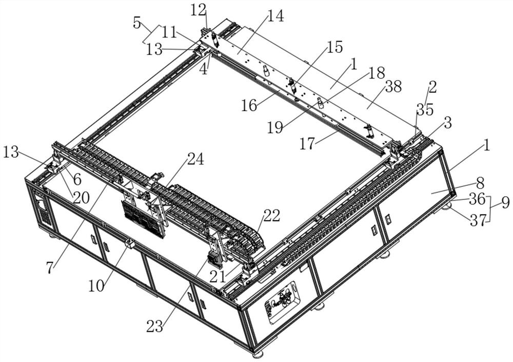
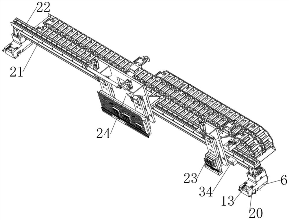
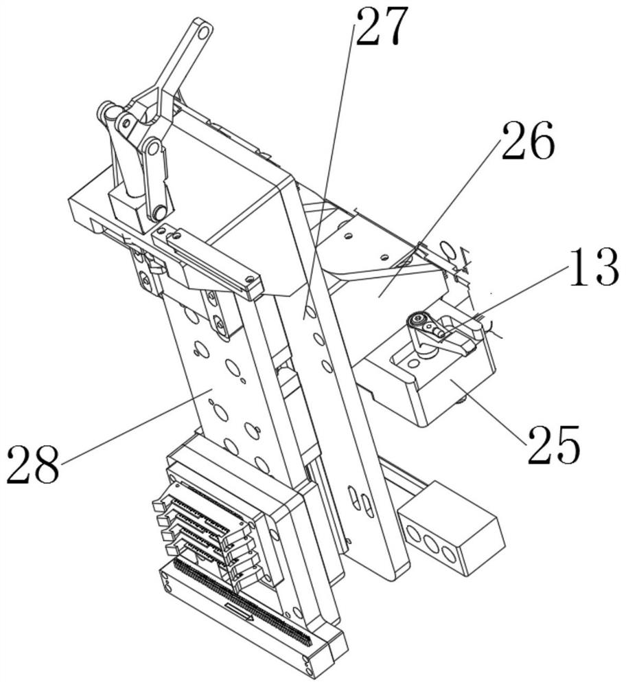
[0021] First of all, the original design intention of the present invention is explained. The capacitive touch screen technology uses the current induction of the human body to work. The capacitive touch screen is a four-layer composite glass screen. The inner surface and interlayer of the glass screen are each coated with a layer of ITO. The outermost layer is A thin layer of silica glass protective layer, the interlayer ITO coating is used as the working surface, four electrodes are drawn from the four corners, and the inner layer of ITO is the shielding layer to ensure a good working environment. During the production process of the electrical capacitance screen, it is necessary to Carry out conduction detection to ensure the service life of the capacitive screen. Most of the existing detection process is through manual detection. This method is low in efficiency and labor-intensive for workers. The detection device has a complex structure, high cost, low detection efficienc...
PUM
 Abstract
Description
Claims
Application Information
PatSnap Eureka turns technology decisions into work you can execute. Powered by our Innovation Knowledge Graph, it runs expert workflows across engineering, life sciences, materials and intellectual property. Get your review-ready output in minutes.


