
Two-stage power converter

A technology of power converters and converters, which is applied in the direction of output power conversion devices, electrical components, and conversion equipment without intermediate conversion to AC. It can solve the problems of resonant frequency changes, complex control, and inability to perform, so as to reduce voltage. stress, high power efficiency, and improved performance

Active Publication Date: 2021-12-24
RICHTEK TECH
View PDF6 Cites 0 Cited by
  • Summary
  • Abstract
  • Description
  • Claims
  • Application Information

AI Technical Summary

Problems solved by technology

In addition, the capacitance value of the capacitor usually decreases with the increase of the DC bias voltage. When the input voltage range is between 36V and 76V, the DC bias voltage range of the capacitor C1 will be between 27V and 57V. The variation range of the bias voltage is wide, so it is known that the capacitance value of the power converter varies considerably, and its resonant frequency also changes with the variation of capacitance
This results in large switching power losses and requires complex controls to vary the power conversion efficiency
Furthermore, the voltage conversion ratio of the input voltage VIN and the output voltage VOUT of this known power converter can only be 4:1 or 2:1, and the voltage conversion ratio of 3:1 cannot be achieved.

Method used


Image

  • Two-stage power converter
  • Two-stage power converter
  • Two-stage power converter

Examples


Embodiment Construction

[0056] The drawings in the present invention are all schematic diagrams, mainly intended to show the coupling relationship between various circuits and the relationship between various signal waveforms. As for the circuits, signal waveforms and frequencies, they are not drawn to scale.

[0057] figure 2 is a schematic block diagram showing a two-stage power converter according to an embodiment of the present invention. Please refer to figure 2 , The two-stage power converter 20 of the present invention includes a resonant switched-capacitor converter (RSCC) 201 , a voltage regulator 202 and a communication interface and control circuit 203 . The voltage regulator 202 is coupled to the resonant switched capacitor converter 201 , and the communication interface and control circuit 203 is coupled to both the resonant switched capacitor converter 201 and the voltage regulator 202 . The resonant switched capacitor converter 201 is used to receive an input voltage Vin to generat...


PUM


Abstract

A two-stage power converter includes: a resonant switching capacitor converter for receiving an input voltage to generate a first-stage voltage; the voltage regulator is used for receiving the first-stage voltage to generate an output voltage; and the communication interface and control circuit is used for generating a charging operation signal, at least one discharging operation signal and a switching signal. The charging operation signal and the at least one discharging operation signal are used for controlling the resonant switching type capacitance converter to respectively carry out a charging program and at least one discharging program. The switching signal is used for controlling the voltage regulator to synchronize a resonant frequency of the resonant switched capacitor converter and a switching frequency of the voltage regulator. The communication interface and the control circuit adjust a delay time after the at least one discharge program ends, and start the charge program at the end of the delay time.

Description

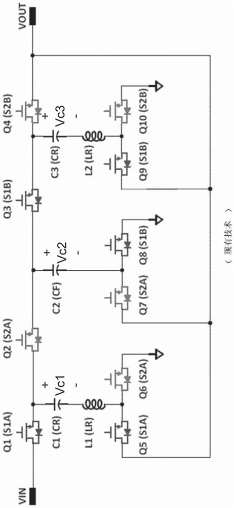
technical field [0001] The invention relates to a two-stage power converter, in particular to a two-stage power converter capable of switching frequency synchronously. Background technique [0002] figure 1 Display known power converters. During the charging operation, the switches Q1, Q3, Q5, Q8, and Q9 are turned on, and the switches Q2, Q4, Q6, Q7, and Q10 are not turned on, so that the capacitor C1 is connected in series with the inductor L1 between the input voltage VIN and the output voltage VOUT, and The capacitor C2 is connected in series with the capacitor C3 and the inductor L2 between the ground potential and the output voltage VOUT. In the discharge operation, the switches Q2, Q4, Q6, Q7, and Q10 are turned on, and the switches Q1, Q3, Q5, Q8, and Q9 are not turned on, so that the inductor L1 is connected in series with the capacitors C1 and C2 between the ground potential and the output voltage VOUT , and the inductor L2 is connected in series with the capaci...

Claims


Application Information

Patent Timeline
Patent Type & Authority Applications(China)
IPC IPC(8): H02M3/07H02M1/44
CPCH02M3/07H02M1/44Y02B70/10
Inventor 刘国基杨大勇白忠龙
Owner RICHTEK TECH
Learn More