Treatment equipment for industrial toxic waste gas

A technology for waste gas and equipment, which is applied in the field of treatment equipment for industrial toxic waste gas, can solve problems such as stuck in the burned through inner wall, leakage, and the impact of penetration of transmission pipelines.

Pending Publication Date: 2021-12-28
李小明
View PDF0 Cites 0 Cited by
  • Summary
  • Abstract
  • Description
  • Claims
  • Application Information

AI Technical Summary

Problems solved by technology

[0003] In summary, the inventors have found that the existing treatment equipment mainly has the following defects: since the refining raw materials of the coking plant are all main raw materials such as gas coal, fat coal, coking coal, etc., the toxic waste gas emitted by smelting coke is even It is in a high-temperature state, and the exhaust gas contains a large number of high-temperature particles, so that the high-temperature gas is directly sent from the conveying pipe to the treatment equipment, the exhaust gas and the contained particles are easy to burn through the inner wall of the conveying pipe through their own high-temperature state, and the particles will be destroyed. It is directly stuck into the inner wall burned through, so that it will cause high-temperature harmful gas to easily cause corresponding penetration effects on the delivery pipeline of the treatment equipment, so as to reduce the balance of the treatment equipment against harmful gases and even cause leakage

Method used


Image

  • Treatment equipment for industrial toxic waste gas
  • Treatment equipment for industrial toxic waste gas
  • Treatment equipment for industrial toxic waste gas

Examples


Embodiment 1

[0028] Figure 1 to Figure 6 Shown:

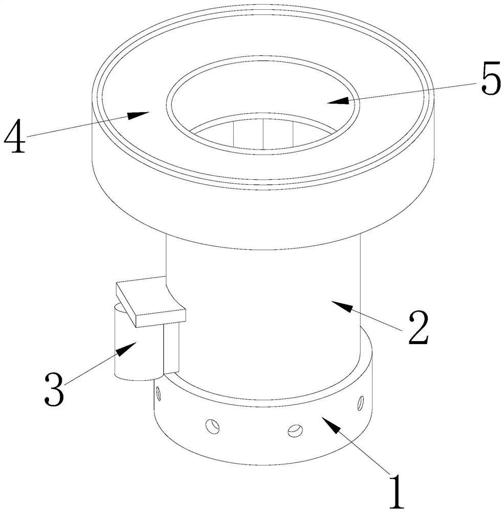
[0029] The invention provides a treatment equipment for industrial toxic waste gas,

[0030] Its structure includes a base 1, a processing end 2, an electric control box 3, an outlet end 4, and a delivery pipe 5. The upper end of the base 1 is attached to the lower end of the processing end 2, and the electric control box 3 is installed on the processing end 2. The side of the outlet end 4 is fixed above the electric control box 3, and the delivery pipe 5 is embedded in the outlet end 4.

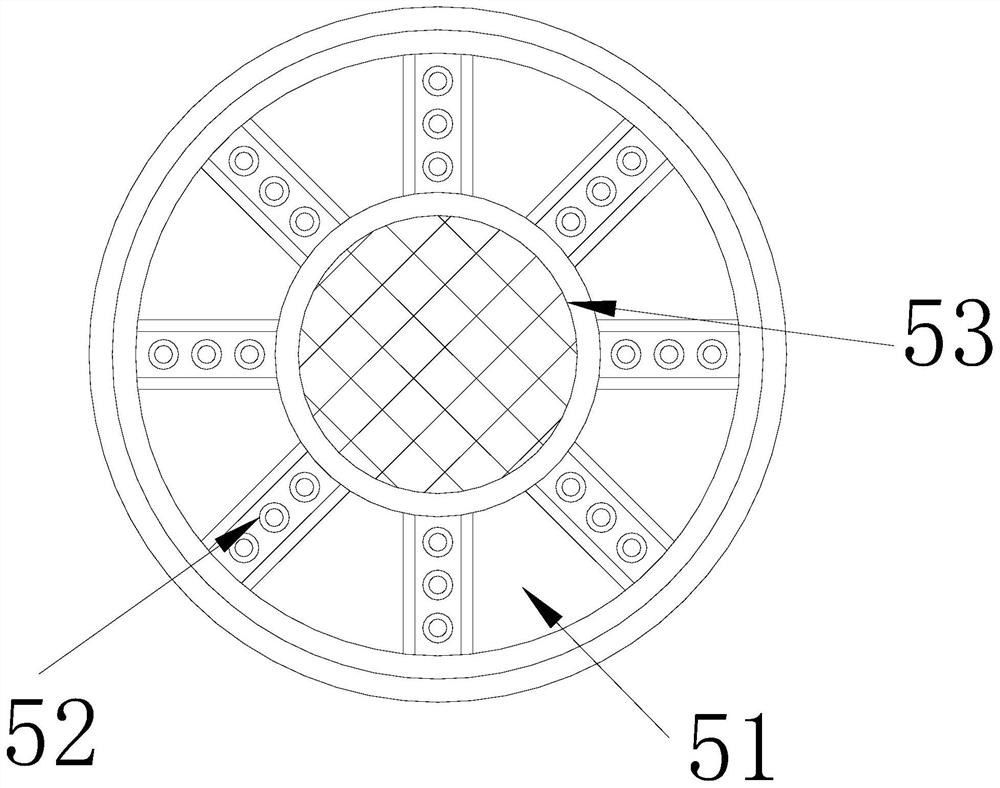
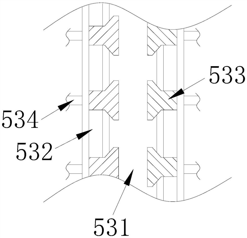
[0031] The delivery pipe 5 is provided with a fixing groove 51, a mounting rod 52, and a through hole 53, the fixing groove 51 is fixedly connected with the mounting rod 52, the through hole 53 is embedded in the mounting rod 52, and the mounting rod 52 There are altogether eight through holes 53 with corresponding gaps therebetween, and the number of the installation rods 52 can enhance the positioning of the through holes 53 .

[0032] Wherein, the ...

Embodiment 2

[0039] Figure 7 to Figure 9 Shown:

[0040] The invention provides a treatment equipment for industrial toxic waste gas,

[0041] Its structure includes that the pipe body a4 is provided with an outer layer c1, a threaded shaft c2, and an auxiliary hole c3, the inner side of the outer layer c1 is integrated with the threaded shaft c2, and the auxiliary holes c3 are installed on both sides of the outer layer c1, A total of four auxiliary holes c3 are provided under the outer layer c1 and form a square shape. The auxiliary holes c3 can effectively strengthen the connection effect of the threaded shaft c2 through four directions under the outer layer c1.

[0042] Wherein, the threaded shaft c2 is provided with a pipe c21, an elastic shaft c22, and a support block c23, the pipe c21 communicates with the elastic shaft c22, the support block c23 is movably connected with the elastic shaft c22, and the elastic shaft c22 is a spring Products, the elastic shaft c22 can quickly reset...


PUM


Abstract

The invention provides treatment equipment for industrial toxic waste gas. The treatment equipment structurally comprises a base, a treatment end, an electric control box, a leading-out end and a conveying pipe, the upper end of the base is attached to the lower end of the treatment end, the electric control box is installed on the side edge of the treatment end, and the leading-out end is fixed to the upper portion of the electric control box. Through improvement of a through hole of the conveying pipe, corresponding aggregation and transmission performance can be improved through a gas channel when toxic waste gas is continuously conveyed, and in the conveying process, external cold water can be guided into the gas channel through a spraying hole of a spray head by utilizing a water pipe so that high-temperature waste gas and particles can be rapidly cooled, and an atomizing net of the spraying hole improves the spraying effect of a water body and prevents the particles from being squeezed into the spraying holes to cause blockage; and the phenomenon that the inner wall of the gas channel is burnt through due to high-temperature waste gas and high-temperature particles is effectively prevented, meanwhile, the corresponding cooling efficiency is improved, blockage caused by the fact that the particles are squeezed into the spraying holes is prevented, and then the subsequent cleaning effect on the gas channel is improved.

Description

technical field [0001] The invention relates to the technical field of industrial harmful waste gas control, in particular to a treatment equipment for industrial toxic waste gas. Background technique [0002] With the rise of chemical plants, coking plants, oil refineries and other production plants, a large amount of toxic waste gas will be generated when specific products are processed and refined, so that the corresponding treatment equipment can effectively control the solubility of toxic waste gas to achieve a relative Emission Standards; [0003] In summary, the inventors found that the existing treatment equipment mainly has the following defects: since the refining raw materials of the coking plant are gas coal, fat coal, coking coal and other main raw materials, the toxic waste gas emitted by smelting coke is even It is in a high-temperature state, and the exhaust gas contains a large number of high-temperature particles, so that the high-temperature gas is direct...

Claims


Application Information

Patent Timeline
Patent Type & Authority Applications(China)
IPC IPC(8): F28C3/06F27D17/00F23J15/06F16L55/00F16L55/24F16L15/00F16L15/08
CPCF28C3/06F23J15/06F27D17/008F16L55/00F16L55/24F16L15/006F16L15/08Y02P10/25
Inventor 李小明
Owner 李小明
Why Eureka
Try Eureka