Flow nozzle

A manufacturing method and the technology of the contact tip, which are applied in the field of the contact tip, can solve the problems of long drilling time and insufficient inner surface precision, etc., and achieve the effects of improving surface quality and tolerance, improving manufacturability, and improving mechanical guidance

Inactive Publication Date: 2004-02-18
ALEXANDER BINZEL SCHWEISSTECHN GMBH & CO
View PDF3 Cites 0 Cited by
  • Summary
  • Abstract
  • Description
  • Claims
  • Application Information

AI Technical Summary

Problems solved by technology

Another disadvantage is that each nominal diameter and each tolerance range requires separate special manufacturing
The disadvantage here is that the drilling takes a relatively long time and the inner surface is produced with insufficient precision

Method used


Image

  • Flow nozzle
  • Flow nozzle
  • Flow nozzle

Examples


Embodiment Construction

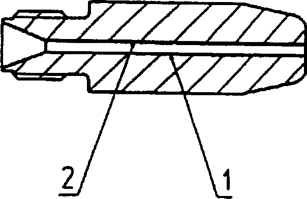
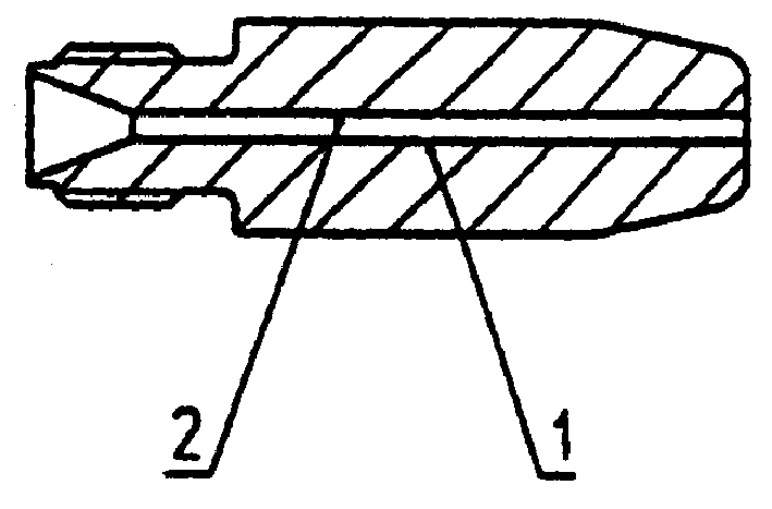
[0019] according to figure 1 , the contact tip 1 is cylindrical, which is the same as the general case. Wherein the apex can be generally conically constricted. The rear area is machined with a thread through which the contact tip is connected to the welding or cutting torch. In this embodiment, the contact tip has a through bore 2 which has a chamfer on the rear side. This way the electrode can be fed in more easily. Such welding tips are in the shape of the prior art.

[0020] The difference here is that the inner bore 2 is deep-drilled in a semi-finished product, which is formed from a solid material or also from a tube. Previously, a tube or part that had already been made hollow was drawn. Relatively speaking, a greater range of material choices is now allowed.

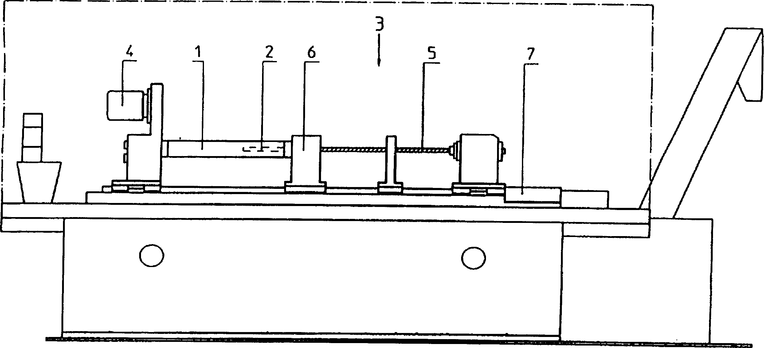
[0021] figure 2 A deep hole drilling machine 3 is schematically shown, and its main components include a driver 4 , a drill bit 5 , a clamping device 6 and a push rod 7 .

[0022] In this exemplary embod...


PUM


Abstract

The invention relates to a flow nozzle (1) for a welding or cutting torch, comprising at least an internal opening (2) for guiding and engaging one or more solder wires, the at least one internal opening (2) being made by deep drilling in raw bar-shaped material, e.g. solid material. This makes it possible to dispense with the use of a drawn raw material which at the same time widening the range of material selection and making the raw material cheaper.

Description

technical field [0001] The invention relates to a contact tip for welding and cutting torches, which has one or more bores for guiding and contacting one or more welding rods. The invention also relates to a method for producing such a contact tip. Background technique [0002] EP 41 165 A1 discloses a gas-shielded welding torch with such a contact tip, which is referred to there as a contact tube. This member is fixedly positioned on top of the gas shielded torch and guides the electrode to the point where the arc starts. At the same time, considerable welding current is sent to the electrode through the contact tip. In this way, due to the effect of current and heat, the contact tip bears a high load, so until now it has been manufactured using drawn copper materials, such as electrolytic copper and copper-chromium-zirconium alloy, and made into hollow semi-finished materials for use. Manufacturing tools and equipment as well as such drawn material manufacturing methods...

Claims


Application Information

Patent Timeline
Patent Type & Authority Patents(China)
IPC IPC(8): B23K9/26B23K9/28
CPCB23K9/282
Inventor 里夏德·扎特勒
Owner ALEXANDER BINZEL SCHWEISSTECHN GMBH & CO
Why Eureka
Try Eureka