

Waste incineration device
A garbage incineration and garbage technology, applied in incinerators, combustion methods, combustion types, etc., can solve the problems of inability to install the internal structure of automatic hot water sterilization flushing, inability to effectively recover metal products, etc., to achieve effective recycling, reducing Effect of upper load
- Summary
- Abstract
- Description
- Claims
- Application Information
AI Technical Summary
Problems solved by technology
Method used
Image

Examples
Embodiment 1
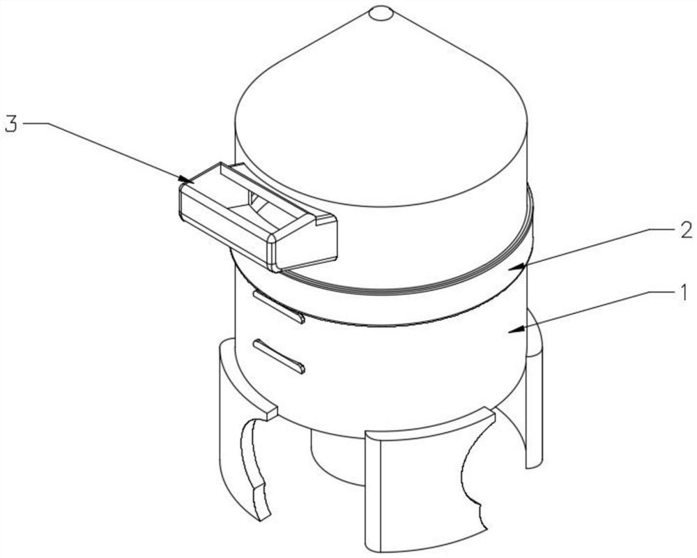
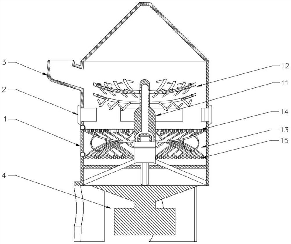
[0028] see Figure 1-7 , the present invention provides a technical solution for a garbage incineration device: comprising a device main body 1, an annular baffle 2 and a garbage hopper 3, the ring baffle 2 is set in the middle of the device main body 1, the garbage hopper 3 and the device The inner side of the main body 1 is communicated and arranged, and the inside of the device main body 1 is equipped with a rotating structure 11, and a collection mechanism 12 is arranged symmetrically on both sides of the upper part of the rotating structure 11, and a cleaning mechanism 13 is arranged symmetrically on both sides of the lower part of the rotating structure 11; The upper part of the inside is provided with a large mesh plate 14, and the inner side of the device main body 1 is located at the bottom of the large mesh plate 14 and is provided with a small mesh plate 15;
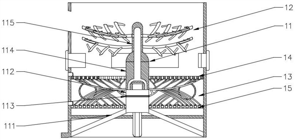
[0029] Such as Figure 2-5 As shown, the rotating structure 11 includes a support base 111, a motor 112, a...
Embodiment 2
[0034] like Figure 1-7 As shown, it includes a device main body 1, an annular baffle 2 and a garbage hopper 3, the annular baffle 2 is sleeved in the middle of the device main body 1, the garbage hopper 3 is communicated with the inside of the device main body 1, and the device main body 1 is equipped with a rotating structure 11, the upper side of the rotating structure 11 is symmetrically provided with a collection mechanism 12, and the lower part of the rotating structure 11 is symmetrically provided with a cleaning mechanism 13; The inner side of the device main body 1 is located at the lower part of the large mesh plate 14 and is provided with a small mesh plate 15;
[0035] like Figure 6-7 As shown, the cleaning mechanism 13 comprises a tree diameter pipe 131, a side branch diameter 132, a lower extension rod 133 and a ring wall 134, and the tree diameter pipe 131 is symmetrically arranged on both sides of the push rod 114, and several side branch diameters 132 are co...
PUM
 Abstract
Description
Claims
Application Information