
Finned radiator for efficient heat dissipation transformer

A heat sink and transformer technology, which is applied in the direction of transformer/inductor cooling, etc., can solve the problems of limiting the flow rate of transformer oil, small flow section of transformer oil, and backlog of oil, so as to increase the flow section area, improve heat dissipation effect, reduce The effect of production costs

Pending Publication Date: 2021-12-31
CHANGSHU YOUBANG RADIATOR
View PDF5 Cites 1 Cited by
  • Summary
  • Abstract
  • Description
  • Claims
  • Application Information

AI Technical Summary

Problems solved by technology

It has the advantages of using two pressing plates to laminate together to form a cooling fin, and using the corrugated shape of the pressing plate to form a cooling liquid channel, thereby increasing the number of cooling liquid channels and the heat dissipation area of ​​the cooling fin, and ensuring the heat dissipation efficiency. , but this technical solution has the common disadvantages of the above-mentioned patent documents and the finned radiators in the prior art: since the radiator adopts two punched steel pipes in the form of a liquid inlet pipe and a liquid outlet pipe, and two The structure of multiple cooling fins is integrated between the liquid inlet pipe and the liquid outlet pipe. With this structure, the flow section of the transformer oil in the steel pipe is small and the resistance is large, which will limit the flow rate of the transformer oil and cause thermal boundary layer thicker, large convective heat transfer thermal resistance, and the problem of poor heat dissipation of the radiator, which cannot further meet the market demand; at the same time, in the prior art, the liquid inlet pipe and the liquid outlet pipe are installed in the height direction of the heat sink At the center of both ends, this will also make the heat dissipation efficiency of different parts of each heat sink different, resulting in unbalanced oil flow in the fin, especially the oil on both sides of the heat sink will backlog and short circuit, resulting in The problem of poor cooling effect

Method used


Image

  • Finned radiator for efficient heat dissipation transformer
  • Finned radiator for efficient heat dissipation transformer
  • Finned radiator for efficient heat dissipation transformer

Examples


Embodiment 1

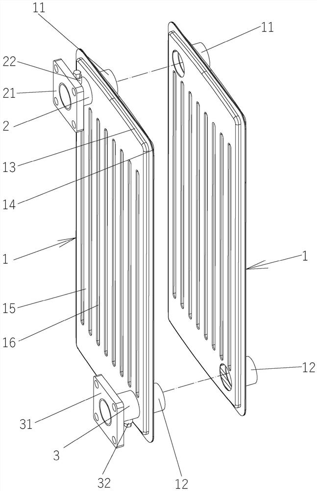
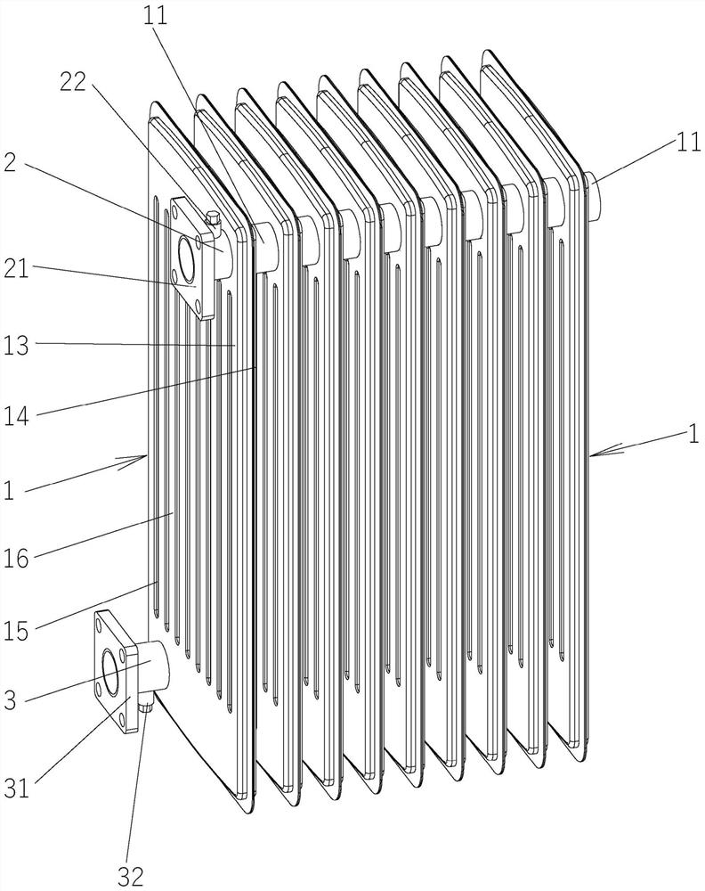
[0021] See figure 1 and figure 2 , which shows a high-efficiency heat dissipation finned radiator for transformers, including a group of heat sinks 1 arranged longitudinally parallel to each other and equidistant from each other. The plurality of heat sinks 1 are all hollow cuboid plate structures and formed inside There is an oil flow chamber.

[0022] As the technical gist of the technical solution provided by the present invention: a first connecting pipe 11 is sleeved at the edge of the body of the heat sink 1 near the top edge and close to the end of the long side of the heat sink 1 , and on the body of the heat sink 1 near the edge of the bottom edge and at the position close to the other long side of the heat sink 1, a second connecting pipe 12 is sleeved, and two adjacent heat sinks 1 pass through the two ends The first connecting pipes 11 and the second connecting pipes 12, which are both provided with openings, communicate with each other, and the positions of the...

Embodiment 2

[0029] In this embodiment, by image 3 and Figure 4 As shown, the first connecting pipe 11 is arranged at the right position close to the top edge of the heat sink 1 , and the second connecting pipe 12 is arranged near the bottom edge of the heat sink 1 At the left part of the edge, an oil circulation circuit with an upper right lower left structure is formed on a group of multiple cooling fins 1 .


PUM


Abstract

A finned radiator for an efficient heat dissipation transformer comprises a set of cooling fins, the multiple cooling fins are of hollow cuboid plate structures, oil circulation cavities are formed in the cooling fins, first connecting pipes are connected to the positions, close to the edges of the top edges and close to the ends of the long edges of one sides of the cooling fins, of bodies of the cooling fins in a sleeved mode, second connecting pipes are connected to the positions, close to the edge of the bottom edges and close to the long edges of the other sides of the cooling fins, of the bodies of the cooling fins in a sleeved mode, every two adjacent cooling fins are communicated through the first connecting pipes and the second connecting pipes with the two ends open, the first connecting pipes and the second connecting pipes correspond to the two ends of the diagonal lines of the end faces of the multiple cooling fins in position, and an oil inlet pipe and an oil return pipe are connected to the cooling fin on the outermost side of one set of multiple cooling fins. The set of cooling fins can conduct heat dissipation on high-temperature oil guided in by an oil inlet pipe through drainage of the first connecting pipes and the second connecting pipes and then guide the high-temperature oil back into the oil return pipe. The heat dissipation area is large, and the heat dissipation effect is improved; and the heat exchange efficiency is improved and the production cost is reduced.

Description

technical field [0001] The invention belongs to the technical field of cooling equipment for transformers, and in particular relates to a high-efficiency heat dissipation sheet radiator for transformers. Background technique [0002] With the rapid development of my country's economy and the rapid growth of the manufacturing industry, the demand for electricity in various fields in our country is also increasing year by year, and the demand for power transformers is also increasing rapidly. Most of the existing transformers are oil-immersed transformers, which are a new type of high-performance transformer with more reasonable structure and better performance. Oil is used as the main insulation method of the transformer and the cooling medium of the transformer. When the power transformer is running, the internal Windings, iron cores and other components will generate losses, which are converted into heat and transferred to the wall of the oil tank through heat conduction an...

Claims


Application Information

Patent Timeline
Patent Type & Authority Applications(China)
IPC IPC(8): H01F27/12H01F27/22
CPCH01F27/22H01F27/12
Inventor 钱柯恒虞礼辉王建忠
Owner CHANGSHU YOUBANG RADIATOR
Learn More