Humidification system for fixed fuel cell power station and control method

A fuel cell and humidification system technology, applied in the direction of fuel cells, fuel cell additives, fuel cell heat exchange, etc., can solve the problems of inability to achieve humidification, low energy utilization, etc., to solve the problem of droplet entrainment and improve energy utilization efficiency, and the effect of ensuring safe operation

Active Publication Date: 2021-12-31
SHANGHAI MICROPOWERS +2
View PDF7 Cites 2 Cited by
  • Summary
  • Abstract
  • Description
  • Claims
  • Application Information

AI Technical Summary

Problems solved by technology

The energy efficiency of the scheme is low
[0010]4. The electric heater in this scheme is installed in the spray pipeline, and the humidification at the set temperature cannot be achieved during the startup process and initial operation of the system

Method used


Image

  • Humidification system for fixed fuel cell power station and control method
  • Humidification system for fixed fuel cell power station and control method

Examples


Embodiment 1

[0051] Embodiment 1: A humidification system for a stationary fuel cell power station.

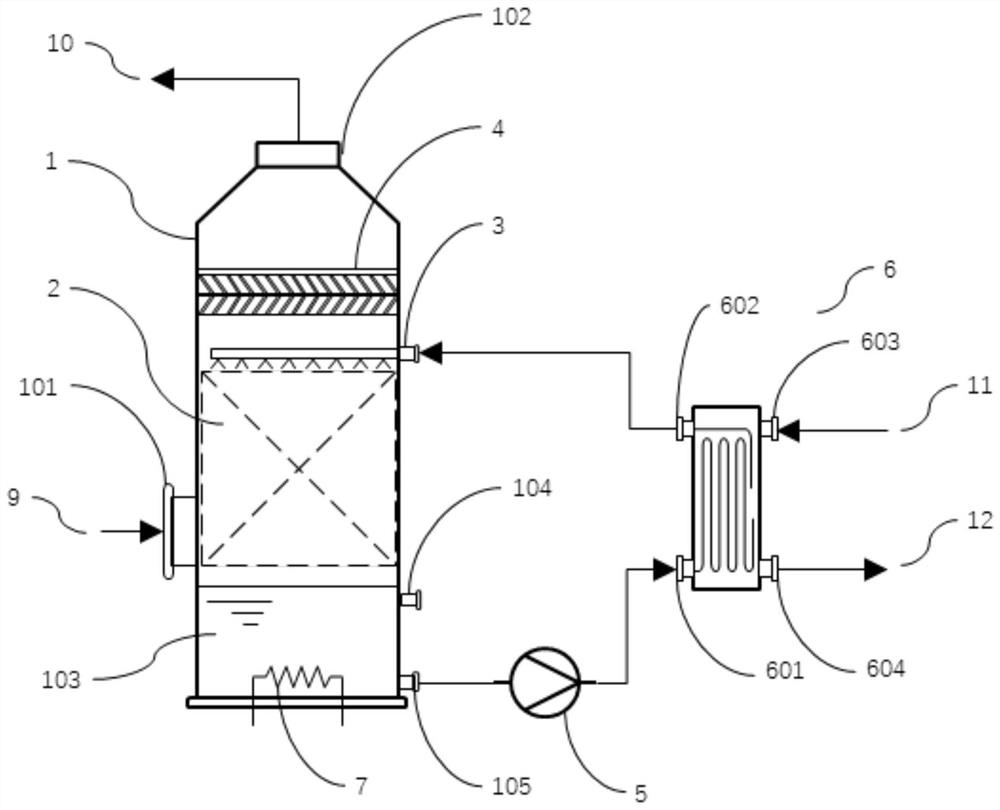
[0052] Such as figure 1 As shown, the humidification system for a stationary fuel cell power station in this embodiment includes a tower body 1 . The tower body 1 has an air outlet 102 at the top and an air inlet 101 at the side. The air inlet 101 is set lower than the air outlet 102 . Between the air inlet 101 and the air outlet 102, the tower body 1 is provided with a packing layer 2, a spray device 3 and a droplet intercepting device 4 from bottom to top; the droplet intercepting device 4 is used to separate the mist entrained in the updraft droplet.

[0053] Before humidification, the reaction gas 9 enters the tower body 1 from the lower air inlet 101 and flows upward, first flows through the packing layer 2, that is, the gas-liquid contact area to complete the humidification process, and then enters the droplet interception device 4 after passing through the spray device 3, Carry ou...

Embodiment 2

[0066] Embodiment 2: A humidification system for a stationary fuel cell power station.

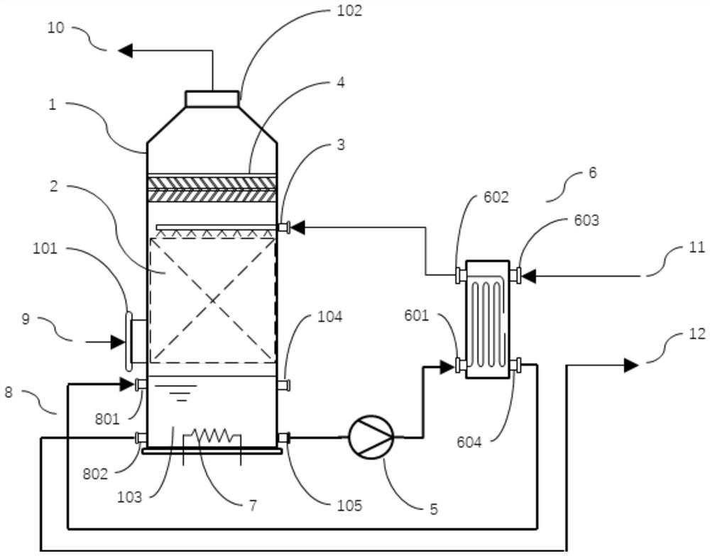
[0067] Such as figure 2 As shown, in this embodiment, on the basis of Embodiment 1, a second waste heat exchanger 8 is also immersed in the water storage tank 103 (only its connection interface is shown in the figure); the second waste heat exchanger 8 has a second The stack circulating water inlet 801 and the second stack circulating water outlet 802 , the second stack circulating water inlet 801 is set higher than the second circulating water outlet 802 . The second waste heat exchanger 8 and the first waste heat exchanger 6 are connected in series to the stack circulating water system of the fuel cell power plant, that is, the second stack circulating water inlet 801 is connected to the first stack circulating water outlet 604, The second stack circulating water outlet 802 and the first stack circulating water inlet 603 are connected to the stack circulating water system of the fuel c...

Embodiment 3

[0070] Embodiment 3: A control method for a humidification system for a stationary fuel cell power station.

[0071] The control method of this embodiment is used to control the humidification system for the stationary fuel cell power station of Embodiment 1, comprising steps:

[0072] S1. Turn on the electric heater 7 to the maximum power, and preheat the water in the water storage tank 103 to 60°C;

[0073] S2. Start the water pump 5, and send a message that the fuel cell power station can start running; at the same time, during the operation of the fuel cell power station, the power of the electric heater 7 is controlled by the PID controller to control the spray circulating water in the spray device 3 Water temperature, the target temperature is 60°C.

[0074] The PID controller not only controls the electric heater 7 according to the water temperature of the spraying circulating water in the spraying device 3, but also according to the changing trend of the water tempera...


PUM


Abstract

The invention provides a humidification system for a fixed fuel cell power station and a control method. The humidification system comprises a tower body, the tower body is provided with an air inlet and an air outlet, a filler layer, a spraying device and a liquid drop intercepting device are sequentially arranged in the tower body between the air inlet and the air outlet, and the spraying device comprises a non-atomized drop spraying head. Water in the water storage tank at the bottom of the tower body is heated by the first waste heat exchanger through the water pump and then pumped to the spraying device. An electric heater and a second waste heat exchanger are further arranged in the water storage tank and used for heating water in the water storage tank. And the waste heat exchanger is connected to an electric pile circulating water system. And the temperature of the electric heater is controlled and heated through the PID controller. The control method comprises the steps that the electric heater is started to the maximum power to preheat water in the water storage tank; and the humidification system and the fuel cell power station are started, and the water temperature of the spraying device is maintained through the electric heater. The system is low in cost, long in service life, easy to control, high in energy utilization efficiency and capable of preventing reaction gas from carrying fog drops.

Description

technical field [0001] The present application relates to the technical field of humidification systems, in particular to a humidification system and control method for a stationary fuel cell power station. Background technique [0002] A fuel cell is an energy converter that directly converts chemical energy in fuel into electrical energy. It has the advantages of high energy conversion efficiency, zero emission, and fast response. For proton exchange membrane fuel cells, the water content of the membrane is an important indicator. When the inlet reaction gas has a relatively high relative humidity, it can ensure that the membrane has sufficient water content. [0003] Fuel cell humidification methods are divided into two types: internal humidification and external humidification. External humidification is divided into bubbling humidification, liquid water jet humidification, membrane humidification, hollow fiber humidification, enthalpy wheel humidification and self-humi...

Claims


Application Information

Patent Timeline
Patent Type & Authority Applications(China)
IPC IPC(8): H01M8/04119H01M8/04007H01M8/04029H01M8/04701H01M8/04828
CPCH01M8/04126H01M8/04134H01M8/04037H01M8/04029H01M8/04723H01M8/04835Y02E60/50
Inventor 杜忠选张林崔立军王林涛刘丰邓笔财李启玉
Owner SHANGHAI MICROPOWERS
Why Eureka
Try Eureka