
Self-stabilization zero amplifying circuit and method for improving gain stability of amplifying circuit

An amplifying circuit and self-stabilizing technology, applied in the field of integrated circuit design, can solve the problems of unfavorable circuit miniaturization design, inability to realize the first signal amplification, increase the complexity of peripheral use, etc., and achieve high integration, improved accuracy, and gain maintenance. stable effect

Pending Publication Date: 2021-12-31
NO 24 RES INST OF CETC
View PDF0 Cites 0 Cited by
  • Summary
  • Abstract
  • Description
  • Claims
  • Application Information

AI Technical Summary

Problems solved by technology

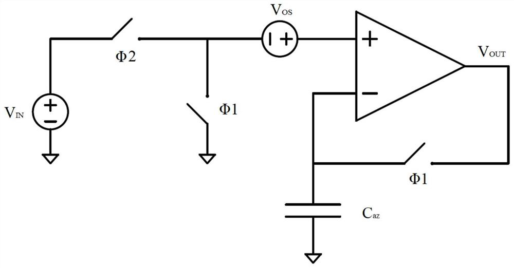
However, there are still problems in the actual use of the traditional auto-zero amplifier: only a set of auxiliary amplifier circuits are used, which work in the zeroing state and the amplifying state respectively, and the amplification of the first signal cannot be realized in the zeroing state, while the analog The first signal is generally a continuous signal. If the first signal changes during the zeroing period, it will not be reflected to the output, resulting in an error signal generated by the second signal during the zeroing and amplification period; offsetting the voltage of the input offset It is stored on the holding capacitor. In order to achieve a stable offset offset voltage, the holding capacitor needs to be very large. It can only be connected with an external capacitor, which increases the complexity of peripheral use and is not conducive to the miniaturization design of the circuit.

Method used


Image

  • Self-stabilization zero amplifying circuit and method for improving gain stability of amplifying circuit
  • Self-stabilization zero amplifying circuit and method for improving gain stability of amplifying circuit
  • Self-stabilization zero amplifying circuit and method for improving gain stability of amplifying circuit

Examples


Embodiment Construction

[0033] The embodiments of the present invention are described below through specific specific examples, and those skilled in the art can easily understand other advantages and effects of the present invention from the contents disclosed in this specification. The present invention can also be implemented or applied through other different specific embodiments, and various details in this specification can also be modified or changed based on different viewpoints and applications without departing from the spirit of the present invention.

[0034] see Figure 1 to Figure 5 . It should be noted that the diagrams provided in this embodiment are only to illustrate the basic concept of the present invention in a schematic way, so the diagrams only show the components related to the present invention rather than the number, shape and the number of components in the actual implementation. For dimension drawing, the type, quantity and proportion of each component can be changed at wi...


PUM


Abstract

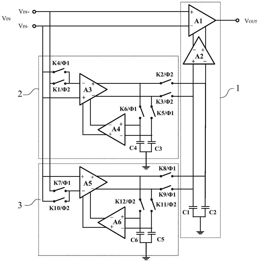
The invention provides a self-stabilization zero amplification circuit and a method for improving gain stability of the amplification circuit, the circuit comprises a main amplification unit, a first auxiliary self-stabilization zero amplification unit and a second auxiliary self-stabilization zero amplification unit, and the first auxiliary self-stabilization zero amplification unit and the second auxiliary self-stabilization zero amplification unit both have a zero setting state and an amplification state. In each clock period, the first auxiliary self-stabilization zero amplification unit and the second auxiliary self-stabilization zero amplification unit alternately work in an amplification state, and the gain of the main amplification unit is kept stable while it is ensured that the offset voltage of the main amplification unit is stably counteracted. Through the structural design of the two auxiliary self-stabilization zero amplification units and in combination with control of clock signals, the two auxiliary self-stabilization zero amplification units alternately work in an amplification state in each clock period, it is guaranteed that the offset voltage of the main amplification unit is stably offset, and the gain of the main amplification unit is kept stable; and spurious signals generated at the output end due to gain error change can be avoided.

Description

technical field [0001] The invention relates to the technical field of integrated circuit design, in particular to an auto-zero amplifying circuit and a method for improving the gain stability of the amplifying circuit. Background technique [0002] In recent years, with the rapid development of intelligent sensing systems represented by the Internet of Things (IOT), the application of sensor products has increased significantly, such as temperature sensors, pressure sensors, infrared photoelectric sensors, etc. It is getting weaker and weaker, and a high-gain operational amplifier circuit is required to amplify the signal, so the requirements for the accuracy of the post-amplifier are also getting higher and higher. The input offset voltage is an important index to characterize the accuracy of the operational amplifier. If the offset voltage is too large, there will be a large DC voltage offset in the output of the operational amplifier. This offset voltage is one of the ma...

Claims


Application Information

Patent Timeline
IPC IPC(8): H03G3/30H03F1/26H03F3/68
CPCH03G3/30H03F1/26H03F3/68Y02D30/70
Inventor 甘明富廖望黄治华何峥嵘
Owner NO 24 RES INST OF CETC
Learn More