Micro-fluidic distribution chip

A microfluidic and chip technology, applied in laboratory utensils, laboratory containers, chemical instruments and methods, etc., can solve problems such as accurate analysis of adverse reaction results, cross-contamination of reaction pools, and limited distribution, and achieve the goal of making Convenience, simple structure, and the effect of improving compatibility

Pending Publication Date: 2022-01-04
BEIJING LEPU WISDOM MEDICAL TECH CO LTD
View PDF2 Cites 0 Cited by
  • Summary
  • Abstract
  • Description
  • Claims
  • Application Information

AI Technical Summary

Problems solved by technology

The invention patent with the authorized publication number CN102671729B discloses a microfluidic chip for multi-index biochemical detection. The reaction pools run through or are connected in parallel, and the isolation between the reaction chambers is realized by using a pneumatic microvalve. The process may cause cross-contamination between reaction pools at different positions, which is not conducive to accurate analysis of reaction results
The invention patent with the authorized publication number CN110075935B discloses a multi-index detection microfluidic cartridge and its application method. The method is based on the rotary valve for sample distribution. Enter different reaction chambers, but this method is complex in structure, high in cost, and limited by space, the number of distributions that can be realized is limited

Method used


Image

  • Micro-fluidic distribution chip
  • Micro-fluidic distribution chip
  • Micro-fluidic distribution chip

Examples


Embodiment 1

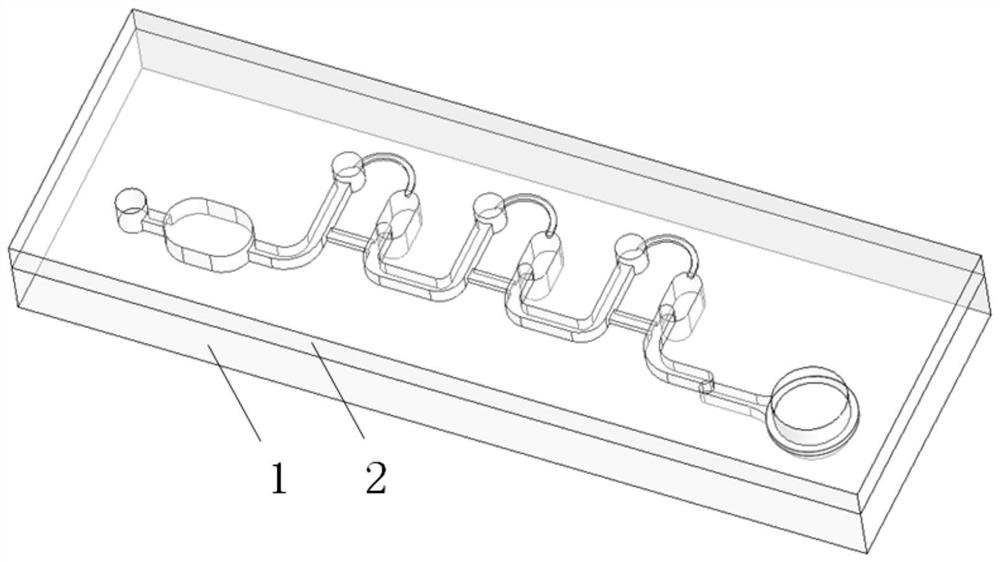
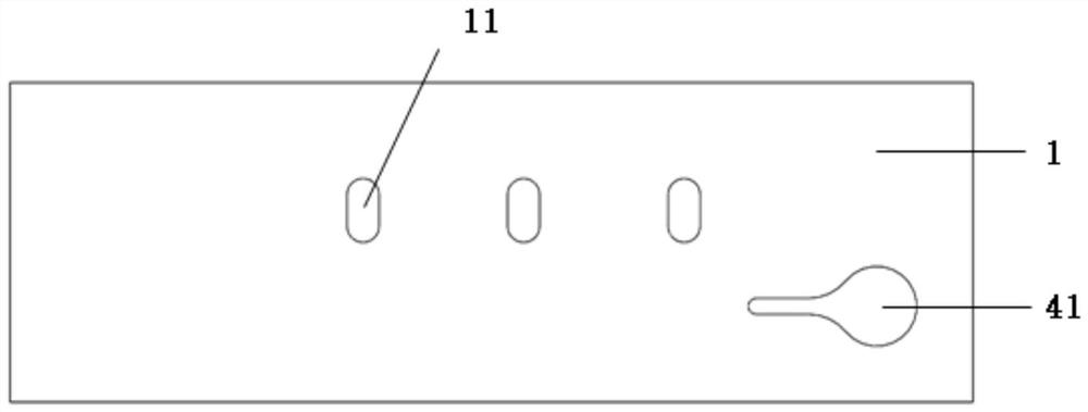
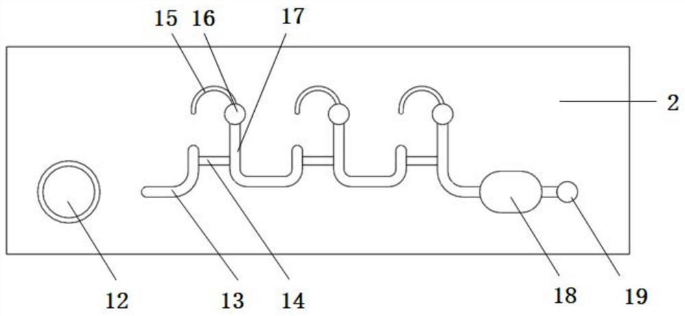
[0033] see Figure 1-Figure 4 , the microfluidic dispensing chip provided in this embodiment includes a chip body 1 and a cover plate 2, and the chip body 1 and the cover plate 2 can be realized by means of double-sided adhesive bonding, thermocompression bonding, ultrasonic welding, laser welding, etc. Seal fit. The chip body 1 is provided with a dispensing cavity 11 , and the cover plate 2 is provided with a sample injection hole 12 , a sample inlet pipe 13 , a bypass pipe 14 , an exhaust pipe 15 , a sample outlet pipe 17 , and an exhaust hole 19 . The sample injection hole 12 , the sample injection pipeline 13 , the distribution chamber 11 , the exhaust pipeline 15 , the sample outlet pipeline 17 , and the exhaust hole 19 are connected in sequence, and the bypass pipeline 14 is connected to the sample inlet pipeline 13 and the sample outlet pipeline 17 .

[0034] The distribution chamber 11 on the chip body 1 and the sample inlet pipe 13 on the cover plate 2, the bypass pi...

Embodiment 2

[0042] Figure 5 and Image 6 Schematically shows the second embodiment of the microfluidic chip provided by the present invention, the microfluidic chip provided by the second embodiment has roughly the same structure as the microfluidic chip provided by the first embodiment, wherein Structures with similar functions are given similar reference numerals, and for the sake of brevity, only the differences are described in detail here.

[0043] Different from the first embodiment, in the second embodiment, all the pipes and cavities are arranged on the chip body 1, that is, the distribution chamber 21, the filter chamber 41, the sample injection hole 22, the sample injection pipe 23, the row Air pipe 25, sample outlet pipe 27, exhaust hole 29, bypass pipe 24 and interface valve 26 are all arranged on the chip body 1. When the depth of the sample inlet pipe 23 and the distribution chamber 21 at the same level are different, in order to avoid A sudden change in the depth of the ...

Embodiment 3

[0045] Figure 7 Schematically shows the third embodiment of the microfluidic chip provided by the present invention, the microfluidic chip provided by the third embodiment has roughly the same components and connections as the microfluidic chip provided by the first embodiment In the relationship, structures with similar functions are given similar reference numerals, and for the sake of brevity, only the differences are described in detail here.

[0046] Different from the first embodiment, in the third embodiment, all the pipes and cavities are arranged on the chip body 1, that is, the distribution chamber 31, the filter chamber 41, the sampling hole 32, the sampling pipe 33, the row Gas pipe 35, sample pipe 37, exhaust hole 39, bypass pipe 34 and interface valve 36 are all arranged on the chip body 1, which is different from the change control of pipe cross-sectional area in the first embodiment and the second embodiment. Flow resistance, this embodiment realizes the orde...


PUM


Abstract

The invention relates to a micro-fluidic distribution chip which comprises a sample adding hole, a sample inlet pipeline, a distribution cavity, an exhaust pipeline, a sample outlet pipeline, an exhaust hole and a bypass pipeline which are sequentially communicated. The bypass pipeline is communicated with the sample inlet pipeline and the sample outlet pipeline and is used for enabling a fluid sample added through the sample adding hole to flow to the sample outlet pipeline through the bypass pipeline after the distribution cavity is filled with the fluid sample, and the trend of the fluid can be controlled by limiting the cross sectional area or depth of each pipeline and cavity. The micro-fluidic distribution chip provided by the invention is simple in structure, convenient to manufacture and convenient to use. The purity of samples can be ensured while automatic distribution of the samples is realized, so that multi-index parallel detection of the samples is completed.

Description

technical field [0001] The invention relates to a microfluidic distribution chip, which belongs to the technical field of microfluidics. Background technique [0002] In the fields of medicine, biology, chemistry, etc., it is often necessary to use a sample for multiple tests and operations, and sample distribution technology is required. The existing sample distribution technology usually needs to use a pipette to draw samples multiple times, and then pour them into different reaction tanks or reaction tubes. This method is easy to introduce impurities during the distribution process, causing pollution; The volume of a single system dispensed cannot be too small. Microfluidic technology is a technology that uses microfluidic chips as the carrier, combines with chemistry, biology and other disciplines, and realizes the analysis and detection process in a miniaturized, integrated and automated platform. Microfluidic technology provides the possibility for the automatic tran...

Claims


Application Information

Patent Timeline
Patent Type & Authority Applications(China)
IPC IPC(8): B01L3/00
CPCB01L3/5027B01L3/502738B01L3/502753B01L2300/0681
Inventor 陈铖张标杨坤乐笑笑朱芸增肖博
Owner BEIJING LEPU WISDOM MEDICAL TECH CO LTD
Why Eureka
Try Eureka