Automatic slitting and winding device for fiberglass gridding cloth
A technology of glass fiber mesh cloth and winding device, which is applied in the direction of winding strips, transportation and packaging, textiles and papermaking, etc. It can solve the problems of increasing the work intensity of workers and increasing labor costs, and achieves the reduction of labor costs, cutting The effect of convenient operation and reduced work intensity
- Summary
- Abstract
- Description
- Claims
- Application Information
AI Technical Summary
Problems solved by technology
Method used
Image
Examples
Embodiment 1
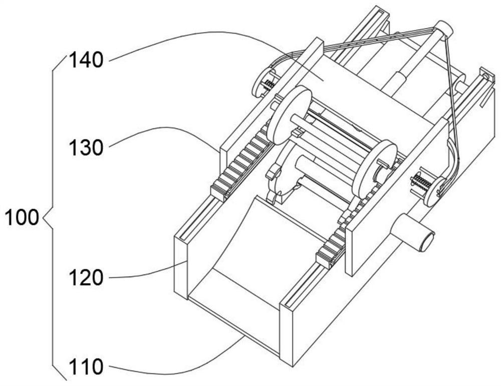
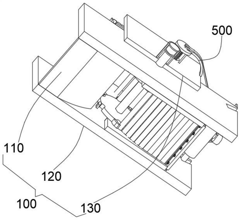
[0050] combine Figure 1-8 As shown, a glass fiber mesh automatic slitting and winding device provided by the present invention includes a basic module 100, a loading and unloading module 200, a winding module 300 and a slitting module 400, and the basic module 100 includes an unloading plate 110 , the vertical plate 120 installed on the front and rear sides of the discharge plate 110, the support plate 130 installed on the outside of the vertical plate 120 and the horizontal plate 140 connected between the two support plates 130; the vertical plate 120 and The support plate 130 cooperates with each other to stabilize the whole device, making the winding and slitting operations more stable. The horizontal plate 140 plays the role of supporting and fixing the electric push rod 480. The unloading plate 110 is used to receive the completed glass fiber coiling. Mesh cloth provides convenience for unloading;
[0051] The loading and unloading module 200 includes a first motor 210 ...
Embodiment 2
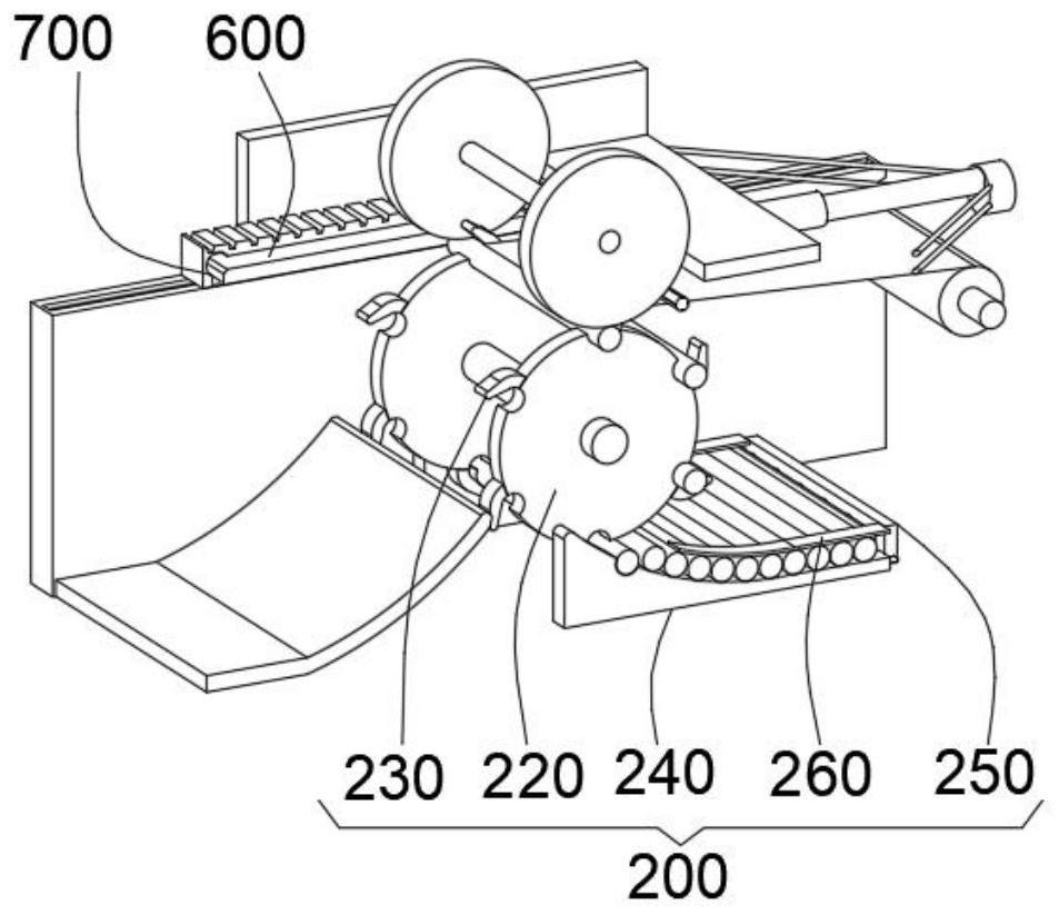
[0060] combine Figure 1-3 and Figure 5-7 As shown, on the basis of Embodiment 1, the two discs 220 are located between the two vertical plates 120, and the discs 220 are provided with a plurality of semicircular openings, and the plurality of semicircular openings The openings are respectively located inside a plurality of hooks 230, the outer side of the disc body 220 is in contact with the inner side of the arc plate 240, the outer side of the arc plate 240 is affixed to the inner side of the vertical plate 120, and the semicircular opening can limit the rod body 340. position to ensure that it can rotate smoothly on the disc body 220.
[0061] Specifically, the rod body 340 is provided in multiples and is adapted to the semicircular opening. The plurality of rod bodies 340 are respectively located between the two disc bodies 220 and between the arc plate 240 and the limit plate 260. With this structural design, the rod body 340 can be continuously replenished to the dis...
Embodiment 3
[0063] combine figure 1 , 3 , 4 and Figure 8 As shown, in the above embodiment, the top of the vertical plate 120 is provided with a trapezoidal chute, and a trapezoidal slider is slidably connected inside the trapezoidal chute, and the trapezoidal slider is installed on the bottom of the tooth plate 420, and the tooth plate 420 meshes with the rack 430, and the trapezoidal chute and the trapezoidal slider cooperate with each other to guide the toothed plate 420, so that the translation of the toothed plate 420 is more stable.
[0064] The working principle and application process of the present invention: in the initial state, a plurality of rod bodies 340 are filled between the arc plate 240 and the limiting plate 260, and then the push plate 280 pushes the plurality of rod bodies 340 to the arc under the extrusion of the thin spring 270. The top of the shaped plate 240 is pushed to provide convenience for the installation of the rod body 340, then the movable end of the ...
PUM
 Abstract
Description
Claims
Application Information
 - R&D
- Intellectual Property
- Life Sciences
- Materials
- Tech Scout
- Unparalleled Data Quality
- Higher Quality Content
- 60% Fewer Hallucinations
Browse by: Latest US Patents, China's latest patents, Technical Efficacy Thesaurus, Application Domain, Technology Topic, Popular Technical Reports.
© 2025 PatSnap. All rights reserved.Legal|Privacy policy|Modern Slavery Act Transparency Statement|Sitemap|About US| Contact US: help@patsnap.com


