Check patentability & draft patents in minutes with Patsnap Eureka AI!

Back-up roll device of plate and strip cold-rolling mill

A technology for cold rolling mills and back-up rolls, which is applied in the direction of counter pressure devices, metal rolling stands, metal rolling mill stands, etc., and can solve problems such as high bearing temperature, oil leakage at the rotating seal, and large consumption of seals, etc. Achieve the effect of meeting the needs of roll rotation, ensuring lubrication and cooling, and improving service life

Pending Publication Date: 2022-01-07
CERI TECH +1
View PDF0 Cites 0 Cited by
  • Summary
  • Abstract
  • Description
  • Claims
  • Application Information

AI Technical Summary

Problems solved by technology

[0004] Forced thin oil lubrication technology, with a large amount of lubricating oil, can effectively lubricate the backup roller bearing and reduce the bearing temperature in theory, but in reality, due to the unreasonable design of the oil inlet and outlet of the backup roller device, a large amount of lubricating oil in the cavity of the bearing seat cannot be discharged in time, resulting in The temperature of the bearing is too high to achieve the purpose of effective cooling; not only that, because the amount of lubricating oil in the cavity of the bearing housing is too large, resulting in a large amount of oil leakage from the rotating seal, polluting the emulsion and the quality of the finished strip, and increasing the lubricating oil, The consumption of emulsion will seriously affect the normal operation of the rolling mill
And because there is no positive pressure in the housing cavity, the emulsion is easy to enter the housing cavity, resulting in damage to the bearing, resulting in complex assembly and maintenance of the support roll, heavy workload, and high consumption of seals, etc.

Method used


Image

  • Back-up roll device of plate and strip cold-rolling mill
  • Back-up roll device of plate and strip cold-rolling mill
  • Back-up roll device of plate and strip cold-rolling mill

Examples


Embodiment Construction

[0040] In order to have a clearer understanding of the technical features, purposes and effects of the present invention, the specific implementation manners of the present invention will now be described with reference to the accompanying drawings.

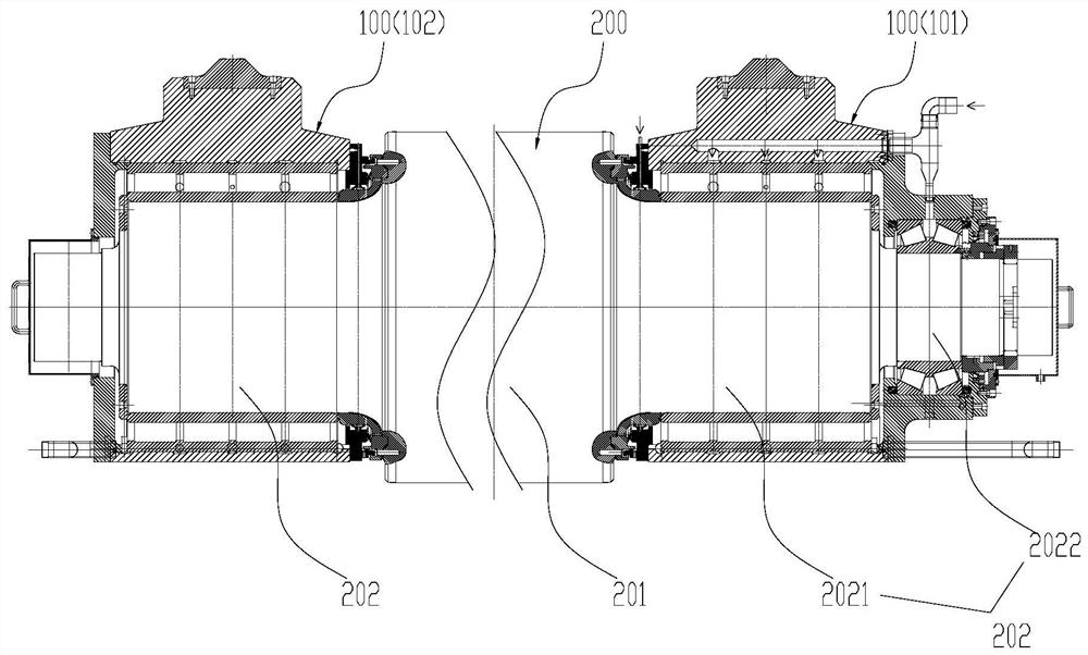
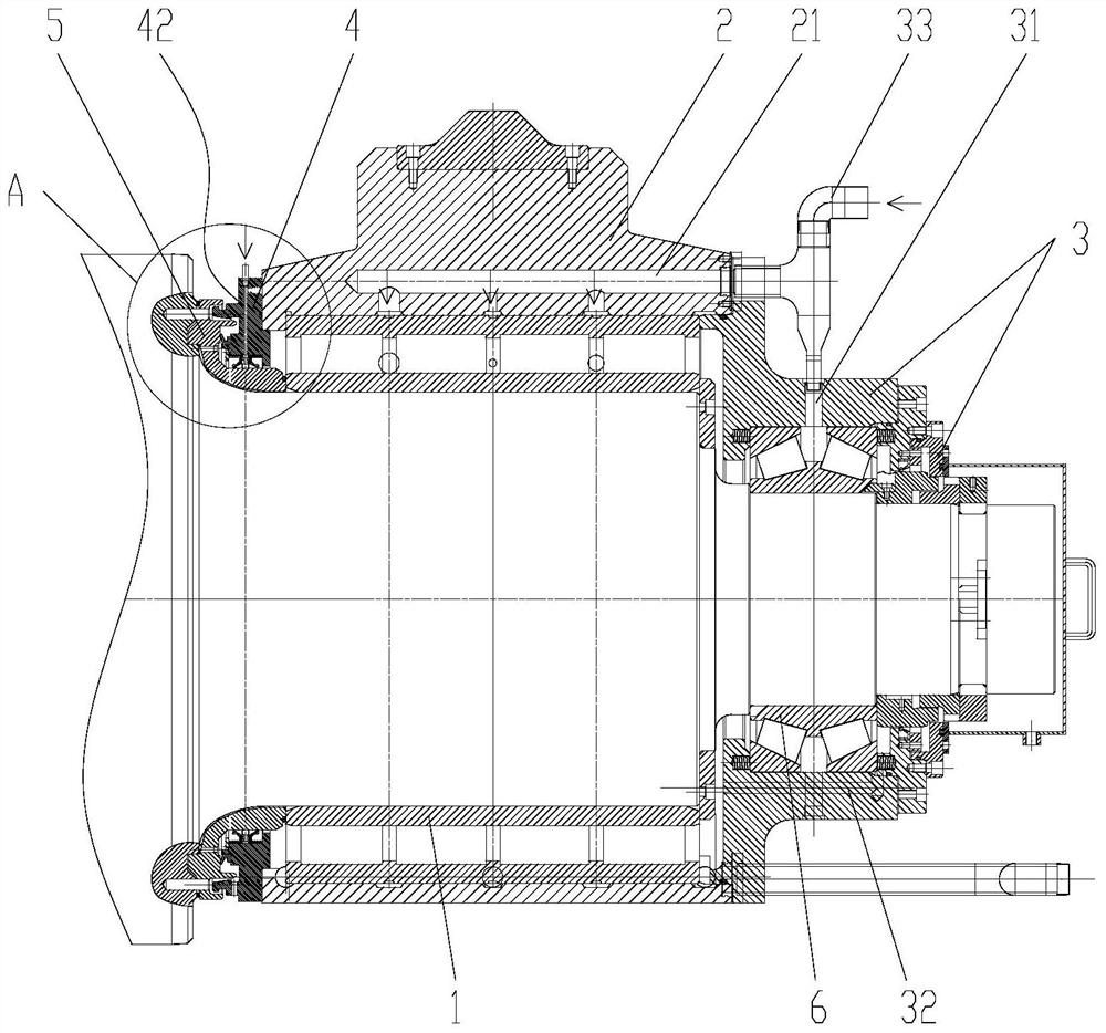
[0041] Such as Figure 1 to Figure 9As shown, this embodiment provides a back-up roll device for a strip cold rolling mill, including a roll 200 and a bearing seat assembly device 100, and the bearing seat assembly device 100 includes a radial bearing 1, a bearing seat 2, an outer end cover 3 and an inner end cover The cover 4 and the radial bearing 1 are sleeved on the roll neck 202 at one end of the roll 200 , the bearing housing 2 is sleeved on the radial bearing 1 , and the outer end cover 3 is fixed on the outer end of the bearing housing 2 . The inner end cover 4 is fixed on the inner side of the bearing seat 2 and sleeved on the roll neck 202 .

[0042] The top of the bearing seat 2 is provided with a first thin oil lubri...


PUM


Abstract

The invention relates to a back-up roll device of a plate and strip cold-rolling mill. The back-up roll device comprises a roll and a bearing seat assembling device, the bearing seat assembling device comprises a radial bearing, a bearing seat, an outer end cover and an inner end cover, and the radial bearing is sleeved on a roll neck at one end of the roll. A first thin oil lubrication oil inlet channel is formed in the top of the bearing seat, and a plurality of circles of first annular oil channels are formed in the inner circumferential face of the bearing seat. At least two thin oil lubrication oil outlet channels are arranged in the bottom of the bearing seat, and the sum of the channel diameters of the thin oil lubrication oil outlet channels is at least two times of the channel diameter of the first thin oil lubrication oil inlet channel. An annular sealing cavity is formed between the inner end cover and the roller neck, an oil seal is arranged in the sealing cavity, an oil gas inlet channel is formed in the inner end cover, and the oil gas inlet channel can communicate with the sealing cavity. According to the invention, the aim that the supporting roller device with the maximum load can stably and reliably run for a long time during high-speed rolling of the plate and strip rolling mill can be achieved.

Description

technical field [0001] The invention relates to the technical field of cold rolling, in particular to a support roll device for a strip cold rolling mill. Background technique [0002] In the fields of cold-rolled strip steel, cold-rolled non-ferrous metals and alloy strips, four-high and six-high mills are widely used to roll strips. The back-up roll device of the rolling mill has a large load and high speed. The back-up roll bearing is the key link affecting the stable rolling of the high-speed strip mill. In order to ensure the good working condition of the back-up roll bearing, it is very important to design and adopt what kind of lubrication and cooling method. [0003] With conventional oil-air lubrication, there is a certain positive pressure in the cavity of the bearing seat, which can effectively prevent the emulsion from entering the cavity and protect the working environment of the backup roller bearing, but there is a weakness in the cooling capacity. Due to the...

Claims


Application Information

Patent Timeline
IPC IPC(8): B21B29/00B21B31/07
CPCB21B29/00B21B31/076
Inventor 刘延军张海东韩志勇
Owner CERI TECH
Features
  • R&D
  • Intellectual Property
  • Life Sciences
  • Materials
  • Tech Scout
  • Unparalleled Data Quality
  • Higher Quality Content
  • 60% Fewer Hallucinations
Learn More