Air-cooling heat dissipation method for digital generator

A technology of digital generator and heat dissipation method, which is applied to the cooling of engines, engine components, machines/engines, etc., can solve the problems of difficulty in ensuring the overall life of the engine, reducing the cooling effect of the engine, and improving the cooling effect. Heat dissipation and cooling effect, scientific cooling path design, and the effect of improving work stability

Pending Publication Date: 2022-01-07
尹登昌
View PDF8 Cites 2 Cited by
  • Summary
  • Abstract
  • Description
  • Claims
  • Application Information

AI Technical Summary

Problems solved by technology

[0006] Therefore, there are following defects in this existing general machine generator: 1. the present structure is that various parts and components are uniformly installed inside the case shell, and each component is located in a large space
However, the invention patent still has the defects of large air flow loss and low cooling efficiency; some structural design defects of the air flow cooling path make it difficult for the air flow to reach places, and it is still difficult to improve the cooling effect after increasing the wind intensity, and the cooling balance is poor. The overall cooling effect of the general machine is difficult to guarantee the improvement of the overall life of the general machine

Method used


Image

  • Air-cooling heat dissipation method for digital generator
  • Air-cooling heat dissipation method for digital generator
  • Air-cooling heat dissipation method for digital generator

Examples


Embodiment 1

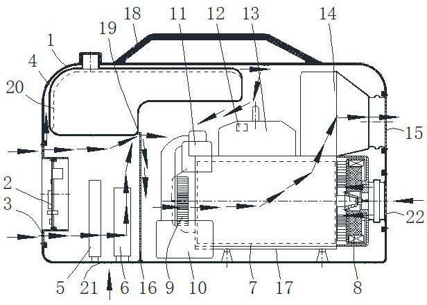
[0065]Embodiment 1: An air-cooled heat dissipation method for a digital generator. In this method, a partition is used to divide the inner cavity of the generator case into a low-temperature area on the left and a high-temperature area on the right, and the air flow is guided from the low-temperature area at the left end of the case. After the air inlet enters, it first flows through the control panel, the controller and the current conversion module (in practice, the current conversion module is a rectifier bridge or an inverter), and then enters the high temperature area on the right through the partition. The improvement is that the high temperature on the right In the area, an engine casing is set at intervals outside the engine main body. The hand-pulled fan as the air flow power is located inside the opening of the left end of the engine casing, so that the air flow in the high temperature area passes through the carburetor and the engine cylinder head outside the engine c...

Embodiment 2

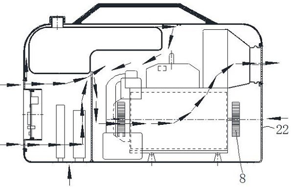
[0092] Embodiment 2, the difference between this embodiment 2 and embodiment 1 is that the figure 2 The digital generator implementation shown. figure 2 The digital generator shown and figure 1 The structures of the digital engines shown are mostly the same, and the only difference is that the installation positions of the generators are different. figure 2 In the digital generator shown, the generator is installed at the left end of the engine (not shown in the figure), and at the same time, the main shaft of the engine is rotatably passed through the engine casing to the right and an auxiliary fan 8 is installed, and the right end surface of the casing is facing the auxiliary fan 8 is provided with auxiliary tuyere 22.

[0093] In this way, it is possible to rely on the auxiliary fan to take in or out the air, so as to improve the cooling effect on the internal components of the chassis shell. During implementation, a second partition part can also be installed at the ...

Embodiment 3

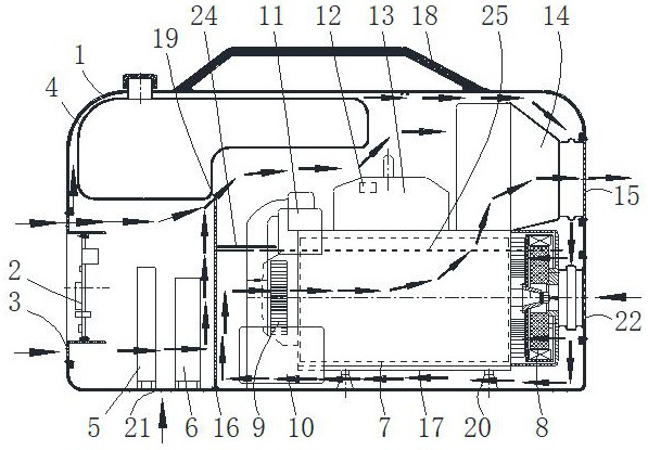
[0094] Embodiment 3, the difference between this embodiment 3 and embodiment 1 is that the image 3 and Figure 4 The digital generator implementation shown. image 3The digital generator shown includes a case shell 1, a control panel 2 is installed in the middle and lower part of the left end surface of the inner cavity of the case shell 1, and a main air inlet 3 is arranged on the case shell corresponding to the control panel 2, and a main air inlet 3 is installed on the upper left part of the inner cavity of the case shell. There is an oil tank 4, a controller 5 and a current conversion module 6 are installed on the lower left part of the inner cavity of the chassis shell 1 (in practice, the current conversion module is a rectifier bridge or an inverter), and an engine 7 is installed on the lower right part of the inner cavity of the chassis shell , the generator 8 is installed on the engine 7, the left end of the engine 7 is provided with a hand-pull fan 9, the air filter...


PUM


Abstract

The invention discloses an air-cooling heat dissipation method for a digital generator. In the method, a partition plate is adopted to divide an inner cavity of a generator case shell into a low-temperature area on the left side and a high-temperature area on the right side, and the method is characterized in that an engine shell sleeves an engine body in the high-temperature area at the right end at an interval; and a hand-pulling disc fan serving as air current power is located in an opening in the left end of the engine shell, so that air current in the high-temperature area enters the engine shell from an opening in the left end of the engine shell after passing through a carburetor and an engine air cylinder head outside the engine shell, flows through a silencer from the upper right portion of an engine after flowing through and cooling the engine, and then flows out of the generator case shell from an air outlet of the silencer, so that internal components of the generator are cooled. The air flow loss is smaller, the cooling path design is more scientific, the cooling efficiency is higher, and the cooling balance is better; and the overall heat dissipation and cooling effect of the generator can be better improved, the working stability of the whole generator is improved, and the overall service life of the equipment is prolonged.

Description

technical field [0001] The invention relates to the technical field of machine cooling, in particular to an air-cooled heat dissipation method for a digital generator. Background technique [0002] A general machine refers to a general-purpose machine equipped with an engine, which is powered by the engine to complete various functions, such as installing a water pump to pump water, and installing a motor for power generation to generate electricity. A general machine generator refers to a small portable generator composed of power generation components installed at the output end of a general machine engine, and is generally used for household use. [0003] In the engine, the gasoline engine is usually composed of two major institutions and five major systems, that is, the crank connecting rod mechanism, the gas distribution mechanism, the fuel supply system, the lubrication system, the cooling system, the ignition system and the starting system. Diesel engines are usually...

Claims


Application Information

Patent Timeline
Patent Type & Authority Applications(China)
IPC IPC(8): F02B63/04F02B77/08F01P1/00F02F7/00
CPCF02B63/044F02B77/08F01P1/00F02F7/007
Inventor 尹登昌
Owner 尹登昌
Why Eureka
Try Eureka