Noise reduction type oil-gas separation device for hydraulic retarder

A technology of hydraulic retarder and separation device, applied in the direction of hydraulic resistance brake, brake type, mechanical equipment, etc., can solve the problems of affecting the braking performance of hydraulic retarder, reducing driving safety, lack of working oil, etc. , to achieve the effect of simple structure, continuous and stable braking performance, and prevention of oil leakage and loss

Inactive Publication Date: 2022-01-07
FUXIN DARE AUTOMOTIVE PARTS
View PDF0 Cites 2 Cited by
  • Summary
  • Abstract
  • Description
  • Claims
  • Application Information

AI Technical Summary

Problems solved by technology

The traditional hydraulic retarder is easy to cause the oil to flow out when the working chamber of the stator and rotor is exhausted, and with long-term use, the oil and gas will gradually lose, which will lead to the lack of working oil in the hydraulic retarder over time, affecting the hydraulic pressure. Force retarder braking performance, reducing driving safety

Method used


Image

  • Noise reduction type oil-gas separation device for hydraulic retarder
  • Noise reduction type oil-gas separation device for hydraulic retarder
  • Noise reduction type oil-gas separation device for hydraulic retarder

Examples


Embodiment Construction

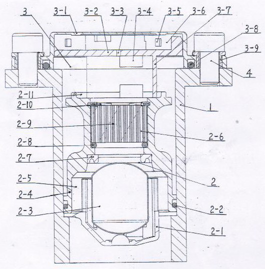
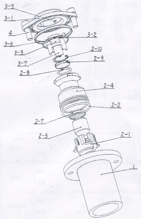
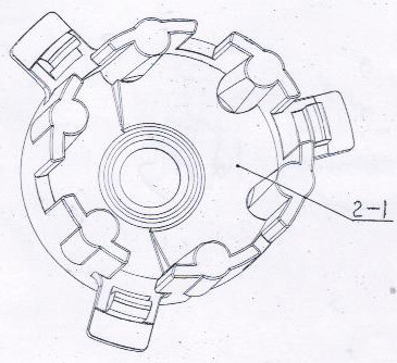
[0012] Examples, see attached Figure 1-4 , The noise-reducing oil-gas separation device for the hydraulic retarder is composed of the middle cover 1, the oil-gas separation assembly 2, and the dust cover assembly 3. The oil-gas separation assembly 2 consists of an oil-gas separation lower cover 2-1, an O-ring 2-2, a floating ball 2-3, an oil-gas separation body 2-4, an oil-resistance chamber 2-5, an oil-gas separation chamber 2-6, a sealing Pad 2-7, O-ring 2 2-8, oil-gas separation plate 2-9, circlip 2-10, oil return tank 2-11, dust cover assembly 3 consists of dust cover 3-1, partition 3-2, ventilation hole 3-3, oil return chamber 3-4, intake and exhaust holes 3-5, intake and exhaust chamber 3-6, partition bracket 3-7, O-ring three 3-8, metal hole Sets of 3-9 compositions. The oil and gas separation lower cover 2-1 of the oil and gas separation assembly 2 is placed in the inner cavity of the middle cover 1, the umbrella edge of the oil and gas separation lower cover 2-1 is...


PUM


Abstract

The invention belongs to mechanical manufacturing equipment, and particularly relates to a noise reduction type oil-gas separation device for a hydraulic retarder. An oil-gas separation lower cover of an oil-gas separation assembly in the noise reduction type oil-gas separation device for the hydraulic retarder is arranged on a boss in an inner cavity of a middle cover through an umbrella edge, an oil-gas separation body of the oil-gas separation assembly is installed on the upper end face of the oil-gas separation lower cover in a pressing mode, a dust cover assembly is installed above the middle cover, a metal hole sleeve is arranged in a connecting hole in a dust cover of the dust cover assembly in an inserted mode, a plurality of air inlet and outlet holes are evenly distributed in the outer circumference of the dust cover, a partition plate and a partition plate support are integrated, an oil return cavity is formed between the partition plate and an oil return groove, an air inlet and outlet cavity is formed between the partition plate and the dust cover, the lower end face of the partition plate support is arranged on the lower end face of the oil return groove of the oil-gas separation body in a pressed mode to be axially fixed, a vent hole communicates with the air inlet and outlet cavity and the oil return cavity respectively, and the air inlet and outlet holes in the dust cover communicate with the air inlet and outlet cavity respectively. The structure is simple, oil leakage and loss can be prevented when the working cavity exhausts air, and air can be exhausted thoroughly.

Description

technical field [0001] The invention belongs to machinery manufacturing equipment, in particular to a noise-reducing oil-gas separation device for a hydraulic retarder. Background technique [0002] The hydraulic retarder is a kind of auxiliary braking equipment. When the hydraulic retarder is closed, the working cavity formed by the stator and the rotor is filled with air. When the hydraulic retarder is working, the oil tank is compressed by compressed air. The internal oil enters the working cavity formed by the stator and rotor, the gas in the working cavity of the stator and rotor will be discharged quickly, and the oil will fill the working cavity formed by the stator and rotor; the oil that participates in the work after the hydraulic retarder works The oil temperature is high, especially when the hydraulic retarder is closed or opened quickly after closing, the oil temperature is high and it is easy to produce mist oil gas. The traditional hydraulic retarder is easy ...

Claims


Application Information

Patent Timeline
Patent Type & Authority Applications(China)
IPC IPC(8): F16D57/00
CPCF16D57/00
Inventor 徐小东李文亮肖遥李思包闯房思奇王忠伟
Owner FUXIN DARE AUTOMOTIVE PARTS
Why Eureka
Try Eureka