Ploughing layer soil stripping device and stripping method thereof

A stripping device and ploughing layer technology, applied in the fields of ploughing equipment, dry gas arrangement, agricultural machinery and implements, etc., can solve the problems of reduced topsoil stripping rate, affecting topsoil stripping benefits, and inability to soil stripping, etc., to ensure the stripping rate, improve the Benefit, prevent damage

Active Publication Date: 2022-01-11
浙江博睿空间规划设计有限公司
View PDF7 Cites 0 Cited by
  • Summary
  • Abstract
  • Description
  • Claims
  • Application Information

AI Technical Summary

Problems solved by technology

The stripping device of the plow layer soil in the above-mentioned patent has the following disadvantages: the stripping device of the above-mentioned plow layer soil cannot strip the soil according to the specific conditions of the soil, and when the soil is too dry or too wet, the topsoil stripping rate is reduced, thereby affecting Benefits of Topsoil Stripping

Method used


Image

  • Ploughing layer soil stripping device and stripping method thereof
  • Ploughing layer soil stripping device and stripping method thereof
  • Ploughing layer soil stripping device and stripping method thereof

Examples


Embodiment 1

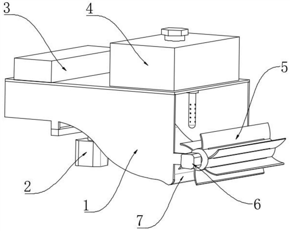
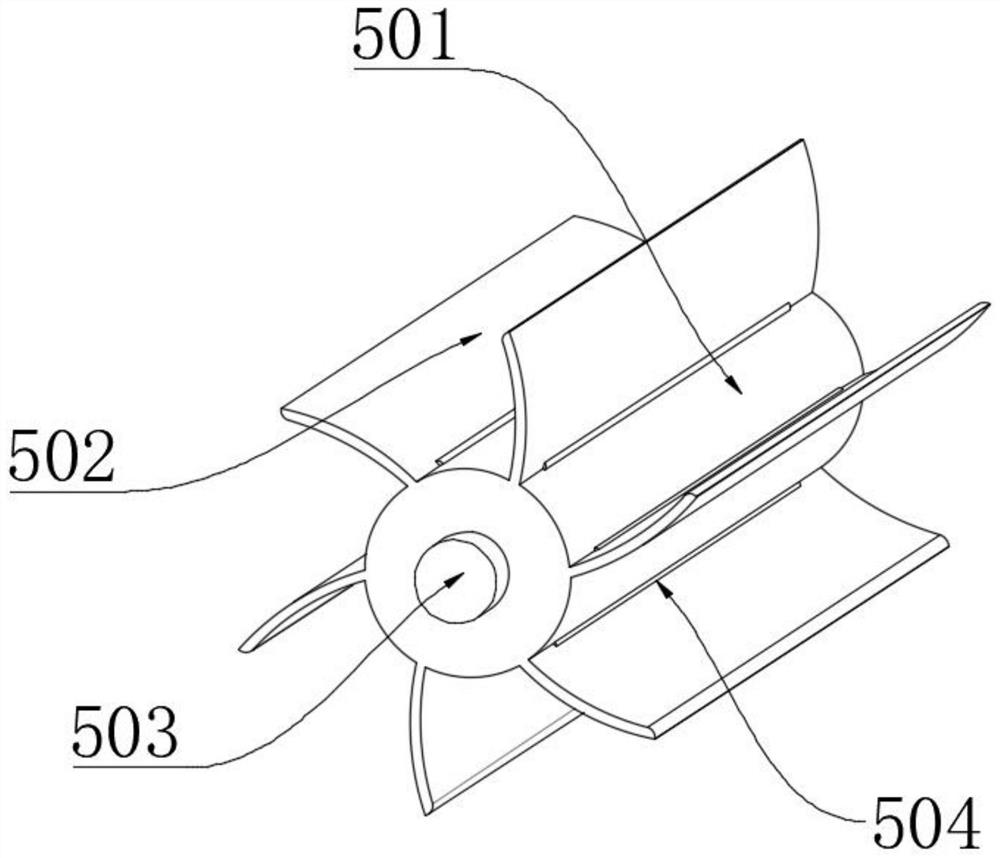
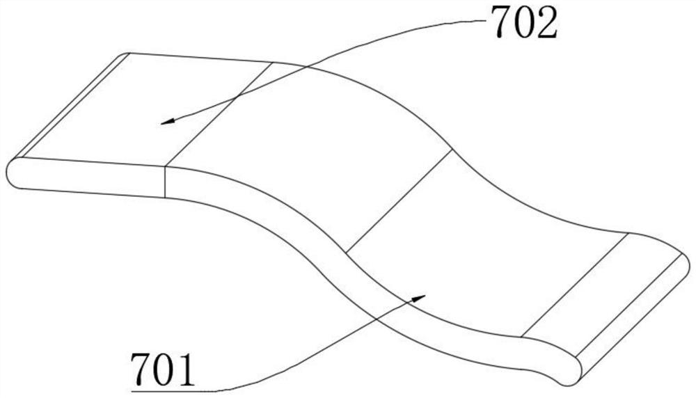
[0045] A stripping device for plow layer soil, such as figure 1 As shown, it includes a peeling shell 1, a hydraulic telescopic machine 2, a peeling mechanism 5, and a transmission mechanism 7; the outer wall of one side of the peeling shell 1 is fixedly connected with a drive motor 6; the outer wall of one side of the output shaft of the drive motor 6 is connected by a coupling On the outer wall of one side of the peeling mechanism 5; the outer wall of the top end of the output shaft of the hydraulic telescopic machine 2 is fixedly connected to the outer wall of the bottom end of the peeling shell 1; Water tank 4; the outer walls on both sides of the transmission mechanism 7 are fixedly connected to the inner wall on one side of the peeling shell 1; the operating hydraulic telescopic machine 2 moves the device up and down to ensure that the soil at the bottom will not be damaged when the soil is peeled off. The surface soil is stripped, and the stripped soil is sent to the tran...

Embodiment 2

[0051] A stripping method of a stripping device for cultivated layer soil, comprising the following steps:

[0052] S1: Survey the soil conditions in the designated project area;

[0053] S2: Evaluate the soil according to the investigation report of the soil condition;

[0054] S3: Formulate a soil stripping utilization plan and estimate the amount of stripped earthwork;

[0055] S4: Install the soil stripping device on the transport vehicle and strip the soil in the area;

[0056] S5: Collect, store and transport the stripped soil to a designated location;

[0057] S6: Return the stripped soil to the designated location, and calculate the amount of soil stripped from the topsoil.

[0058] The formula for calculating the amount of stripped soil from the topsoil is:

[0059]

[0060] Q-soil stripping amount in the stripping area, m 3 ;

[0061] h i -The stripping thickness of the i-th topsoil stripping unit, m;

[0062] S i -The stripping area of ​​the i-th topsoil...


PUM


Abstract

The invention discloses a ploughing layer soil stripping device and a stripping method thereof, relates to the technical field of soil stripping, and aims to solve the problem that the surface soil stripping rate of ploughing layer soil stripping is low. The device comprises a stripping shell, a hydraulic telescopic machine, a stripping mechanism and a conveying mechanism. The method comprises the following steps that the soil condition of a designated project area is investigated. The hydraulic telescopic machine is operated to move the device up and down, it is guaranteed that bottom soil is not damaged during soil stripping, surface soil of a ploughing layer is stripped through the stripping mechanism, the stripped soil is conveyed into the conveying mechanism through operation of the stripping mechanism, and the conveying mechanism conveys the surface soil for conveying; and the soil is humidified or air-dried through an air compression blower and a water storage tank according to the actual condition of the soil, so that the situation that the soil stripping rate is low due to the fact that the soil of the ploughing layer is too wet or too dry in the stripping process is avoided, and the soil stripping rate is guaranteed.

Description

technical field [0001] The invention relates to the technical field of soil stripping, in particular to a stripping device and a stripping method for plow layer soil. Background technique [0002] Topsoil stripping refers to the stripping of the surface soil suitable for cultivation involved in the land occupied by construction or open-pit mining, including temporary or permanent land, and used for in-situ or off-site land reclamation, soil improvement, land reclamation and other purposes The general term for a series of related technologies such as stripping, storage, transportation, plow layer structure and detection. At present, in the prior art, the soil in the plow layer is easily lost due to various factors during the stripping process of the soil, which makes the topsoil stripping rate relatively high. Low, thereby reducing the benefit of topsoil stripping, therefore, need badly a kind of stripping device and stripping method of plow layer soil. [0003] After retrie...

Claims


Application Information

Patent Timeline
Patent Type & Authority Applications(China)
IPC IPC(8): A01B49/04A01B33/10A01B33/12A01B33/08F26B21/00
CPCA01B49/04A01B33/10A01B33/12A01B33/082A01B33/087F26B21/001
Inventor 张晓芳曾凡义巫顺金
Owner 浙江博睿空间规划设计有限公司
Why Eureka
Try Eureka