Composite energy storage system based on deep well

A composite energy storage and deep well technology, applied in the field of composite energy storage systems, can solve the problems of limited utilization of underground space, lack of flexibility in site selection, limited abandoned mines, etc. Implementation, the effect of small terrain requirements

Active Publication Date: 2022-01-11
INST OF ELECTRICAL ENG CHINESE ACAD OF SCI
View PDF4 Cites 4 Cited by
  • Summary
  • Abstract
  • Description
  • Claims
  • Application Information

AI Technical Summary

Problems solved by technology

Typical cases include: ①Scotland Gravitricity Company used electric winches to lift the gravity energy storage of abandoned drilling rigs based on abandoned mines (see Science, 2021, 372 , 446 for details); The utilization rate of underground space is very limited, resulting in limited energy storage, limited available abandoned mines, and lack of flexibility in site selection
②Switzerland Energy Vault uses dobby tower cranes and concrete prefabricated blocks to stack concrete cement prefabricated blocks with dobby tower cranes alternately and non-stop to build blocks at high altitudes, thereby completing the storage and release of electric energy and gravity; The energy is high, but the concrete prefabricated blocks stacked very high on the ground are greatly affected by wind and other weather, and there is a risk of collapse

Method used


Image

  • Composite energy storage system based on deep well
  • Composite energy storage system based on deep well
  • Composite energy storage system based on deep well

Examples


Embodiment 1

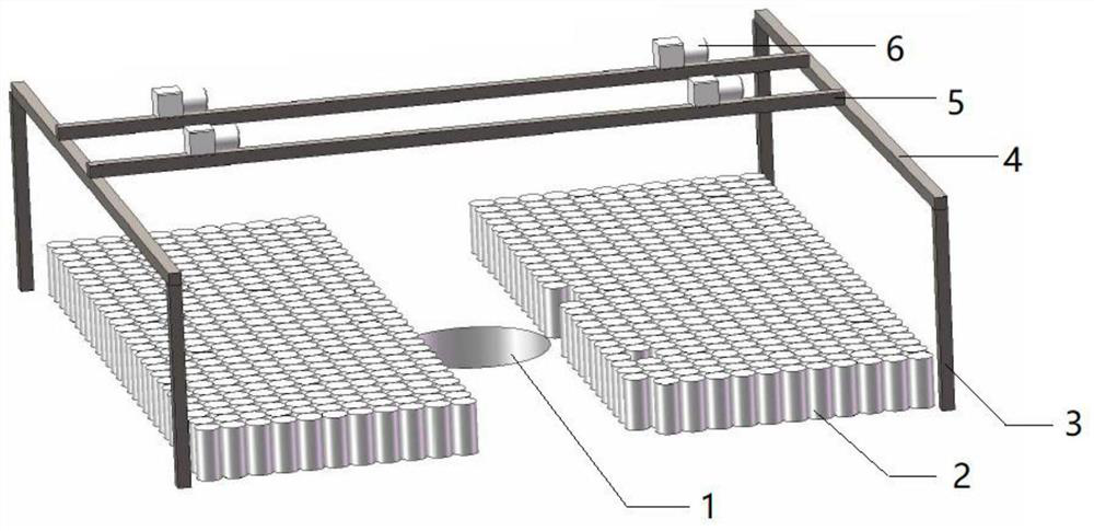
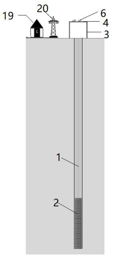
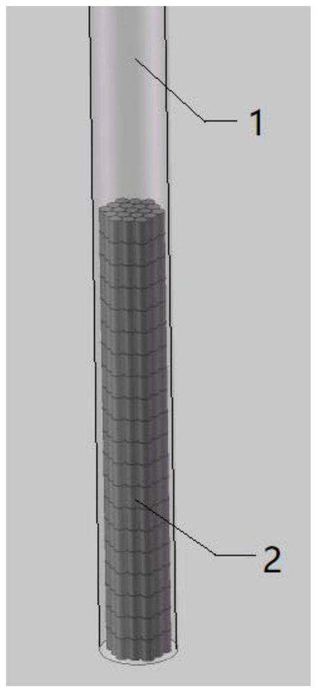
[0054] Refer to attached figure 1 And accompanying drawing 2, the first aspect of the present invention provides a kind of compound energy storage system based on deep well, and this system comprises control center, deep well system 1, weight module 2, gravity lifting device and flow conversion device 19, gravity lifting device , the converter device are connected with the control center 21 signal;

[0055] The gravity lifting device includes a support assembly 3, a truss 4, a beam 5 and a motor generator 6, the support assembly is arranged on the ground; the truss is arranged on the top of the support assembly along the first direction, the crossbeam is arranged on the truss along the second direction, and the second direction It is arranged horizontally and perpendicularly to the first direction, and the beam and the truss are movably connected; the motor generator is movably installed on the beam; in this embodiment, the supporting components are two sets of columns, and th...

Embodiment 2

[0065] In addition to using the deep well for gravity energy storage, the invention can also use the deep well cavity for compressed air energy storage after all the heavy modules are lifted to the ground. One well can be used for two purposes, which greatly improves the total amount of electric energy storage and energy storage density. On the basis of deep well gravity energy storage, a compressed air energy storage device is added, mainly including a movable sealing device and an electric energy-compressed air potential energy conversion device.

[0066] Refer to accompanying drawing 3 to attached Figure 7 , the second aspect of the present invention provides a deep well-based composite energy storage system, the energy storage system includes a control center, a deep well system, a weight module, a gravity lifting device, a flow conversion device and a compressed air energy storage device, and the gravity lifting The device and the flow conversion device are connected wit...


PUM


Abstract

The invention belongs to the technical field of mechanical energy storage, aims to solve the problem that high-efficiency and safe large-capacity energy storage cannot be realized in the prior art, and particularly relates to a composite energy storage system based on a deep well. The system comprises a control system, the deep well, a weight module, a gravity lifting device, a converter device and a compressed air energy storage device, wherein the gravity lifting device comprises a supporting assembly, a truss, a cross beam and a motor generator; the cross beam is movably connected with the truss; the motor generator is movably arranged on the cross beam; the compressed air energy storage device comprises a movable sealing device used for controlling opening and closing of the deep well preset cavity and a conversion device used for conducting conversion control over potential energy and electric energy of compressed air; the conversion device comprises an air compressor, an expansion machine, an air inlet pipeline, an air outlet pipeline, an air inlet valve and an air outlet valve, wherein the air compressor is communicated with the preset well cavity through the air inlet pipeline; and the expansion machine is communicated with the preset well cavity through the air outlet pipeline. The system is extremely small in occupied area, high in energy storage capacity, low in manufacturing cost and high in safety.

Description

technical field [0001] The invention belongs to the technical field of mechanical energy storage, and in particular relates to a composite energy storage system based on deep wells. Background technique [0002] It is a major trend in today's energy field to vigorously develop renewable energy and realize clean energy transformation. However, renewable energy power generation is greatly affected by climatic conditions, resulting in large fluctuations, and poor adjustment and inertia support capabilities. Its large-scale grid connection will affect the real-time power balance and stability of the grid, resulting in curtailment of wind and light. And so on. Energy storage technology can effectively solve the problems of space-time mismatch and grid-connected stability, and is an important guarantee for the large-scale and efficient development and utilization of renewable energy and the realization of my country's green and sustainable energy development strategy. As more an...

Claims


Application Information

Patent Timeline
Patent Type & Authority Applications(China)
IPC IPC(8): E21D7/00E21F13/00F01K27/00F01K13/00F01K13/02F03G3/00
CPCE21D7/00E21F13/00F01K27/00F01K13/00F01K13/02F03G3/00
Inventor 肖立业张京业邱清泉聂子攀王粟唐文冰郭文勇
Owner INST OF ELECTRICAL ENG CHINESE ACAD OF SCI
Why Eureka
Try Eureka