Array antenna damaged unit diagnosis method based on matrix pencil method

A technology of array antenna and diagnosis method, which is applied in the directions of antenna radiation pattern, special data processing application, complex mathematical operation, etc. It can solve problems such as slow recovery calculation speed, difficulty in meeting diagnosis requirements, and enlarged search area, and achieve outstanding engineering applications The effect of high value, strong degree of freedom of sampling points, and small computational complexity

Active Publication Date: 2022-01-11
SOUTHWEST JIAOTONG UNIV
View PDF5 Cites 0 Cited by
  • Summary
  • Abstract
  • Description
  • Claims
  • Application Information

AI Technical Summary

Problems solved by technology

However, the recovery calculation speed of the diagnostic method based on compressed sensing is too slow, and this method will lead to an increase in the search area of ​​the optimal point and an increase in computing time with the expansion of the array size; on the other hand, the diagnostic method based on compressed sensing cannot Guarantee the best sparsity. In the case of large noise interference, the inverted small unit excitation will affect the judgment of the diagnosis result, and it is difficult to meet the diagnosis needs of large arrays and damaged units under sampling data in harsh environments.

Method used


Image

  • Array antenna damaged unit diagnosis method based on matrix pencil method
  • Array antenna damaged unit diagnosis method based on matrix pencil method
  • Array antenna damaged unit diagnosis method based on matrix pencil method

Examples


Embodiment approach

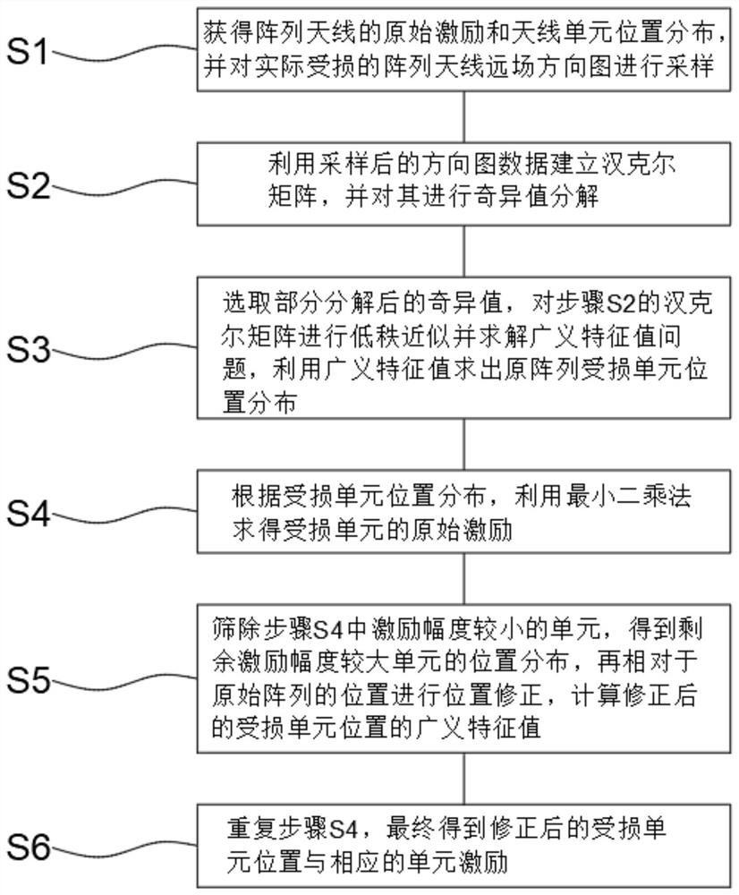
[0062] Implementation method: 32-element half-wave spacing antenna line array;

[0063] The array is composed of N=32 unit ideal omnidirectional antennas, the antenna spacing is λ / 2, and λ is the free space wavelength; the excitation of the antenna unit adopts Chebyshev comprehensive weighting with side lobe level SLL=-30dB; set the damaged unit Number N F = 3, randomize the N in the array F unit is set as damaged, and the excitation of the damaged unit is set to 0; set the sampling coefficient M=20, the bundle parameter L=M, the number of singular values ​​q=10; finally, in the process of pattern sampling, apply signal to the sampled signal Gaussian white noise with a noise ratio of SNR=20dB; the damaged unit of the above-mentioned 32-unit half-wave spacing antenna line array is diagnosed through the specific steps in the method of the present invention.

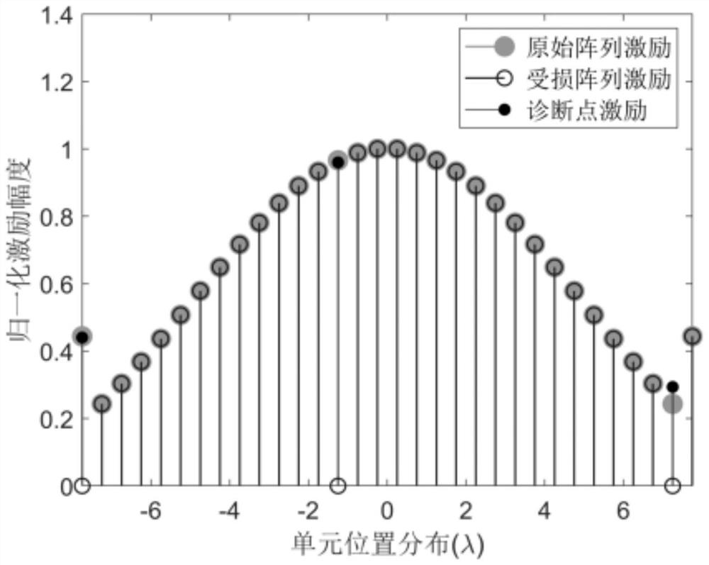
[0064] Such as figure 1 The results shown correspond to the comparison of the original array excitation, damaged array...


PUM


Abstract

The invention relates to an array antenna damaged unit diagnosis method based on a matrix beam method, and the method comprises the steps: S1, obtaining the original excitation of an array antenna and the position distribution of antenna units, and carrying out the sampling; S2, establishing a Hankel matrix by using the sampled directional diagram data, and performing singular value decomposition on the Hankel matrix; S3, selecting a singular value to carry out low-rank Hankel matrix approximation, and PERFORMING solving to obtain a generalized eigenvalue; S4, obtaining the original excitation of the damaged unit according to the position distribution of the damaged unit; S5, screening out units with small excitation amplitudes in the step S4, correcting the positions of the damaged units, and calculating generalized characteristic values of the positions of the corrected damaged units; and S6, repeating the step S4 to obtain the corrected damaged unit position and the corresponding unit excitation. According to the array antenna damaged unit diagnosis method provided by the invention, the position and excitation of the damaged unit of the array can be quickly diagnosed, the sensitivity to noise is extremely low, and the diagnosis of the array can be completed under relatively strong noise interference.

Description

technical field [0001] The invention relates to the technical field of diagnosis of a damaged unit of an array antenna, in particular to a method for diagnosing a damaged unit of an array antenna based on a matrix beam method. Background technique [0002] With the development of wireless communication systems such as satellite communication, radar and remote sensing, the demand for array antennas, especially active phased array antennas, has increased significantly. Because these applications have strict requirements on high-performance antenna systems, when the array antenna has poor radiation characteristics, it is an important engineering task to detect some antenna unit failures and compensate for these failure units. In the event of an active phased array antenna failure, the desired far-field pattern is usually maintained by appropriately changing the feed distribution of non-faulty elements rather than removing the faulty element. Since detection is the first step i...

Claims


Application Information

Patent Timeline
Patent Type & Authority Applications(China)
IPC IPC(8): G06F17/16G06F30/20G01R29/10
CPCG06F17/16G06F30/20G01R29/10Y02D30/70
Inventor 廖成柏果程有峰张胤
Owner SOUTHWEST JIAOTONG UNIV
Why Eureka
Try Eureka