Alignment device and alignment method for mass transfer of micro LED through laser assistance

A laser-assisted and alignment device technology, which is applied to parts of gas lasers, lasers, laser parts, etc., can solve the problems of inconvenient adjustment of optical mask and laser spot adjustment, and achieve high requirements for lens cleanliness and structure Simple, high-risk effects

Pending Publication Date: 2022-01-11
HUAZHONG UNIV OF SCI & TECH
View PDF0 Cites 0 Cited by
  • Summary
  • Abstract
  • Description
  • Claims
  • Application Information

AI Technical Summary

Problems solved by technology

However, because some lasers are dangerous, such as excimer laser, etc., these optical paths are usually sealed, which makes it inconvenient to adjust the optical mask, because the position and shape of the optical mask will directly affect the patterned laser on the processing surface The position and shape of the spot, so the adjustment of the laser spot is inconvenient

Method used


Image

  • Alignment device and alignment method for mass transfer of micro LED through laser assistance
  • Alignment device and alignment method for mass transfer of micro LED through laser assistance
  • Alignment device and alignment method for mass transfer of micro LED through laser assistance

Examples


Embodiment Construction

[0029] In order to make the objects, technical solutions and advantages of the present invention, the present invention will be further described in detail below with reference to the accompanying drawings and examples. It should be understood that the specific embodiments described herein are for explaining the present invention and is not intended to limit the invention. Further, the technical features according to each of the various embodiments described below can be combined with each other as long as they do not constitute a collision between each other.

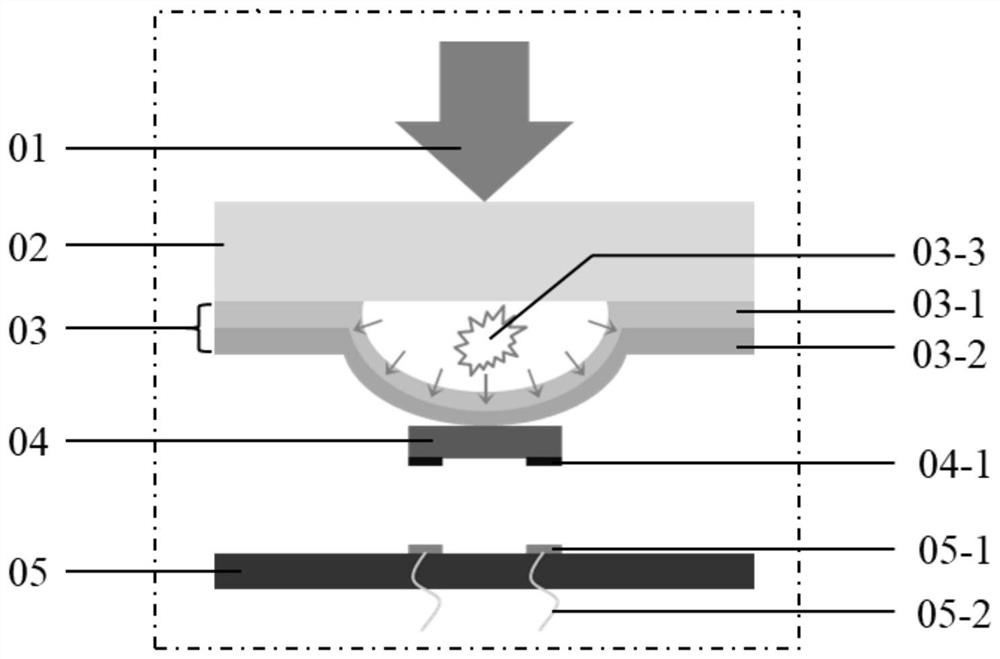
[0030] The laser assisted huge amount of transfer microled assists in the present invention is suitable for use in the process of laser assisted huge amounts of microled. like figure 1As shown, the principle of laser transfer is as follows: The laser spot patterning apparatus forms a patterned laser array spot, and the spot is irradiated on the power release layer 03 by the transparent substrate 02, and the power release l...


PUM


Abstract

The invention belongs to the related technical field of micro LED mass transfer, and discloses an alignment device and an alignment method for mass transfer of a micro LED through laser assistance, and the device comprises a mask projection assembly which comprises a self-defined mask plate and a mask plate fine adjustment device; the self-defined mask plate is provided with a hollow pattern; the mask plate fine adjustment device comprises a manual rotary table, a Z-direction displacement table and an X-direction displacement table which are connected in sequence; the self-defined mask plate is connected to the end part of the manual turntable; a camera alignment system comprises at least two cameras, a cross wire is arranged in the view center of each camera, and each camera is arranged on the corresponding Y-direction displacement table; and a motion platform system comprises a chip motion module and a drive circuit motion module, and alignment and positioning of a light spot, a chip and a drive circuit are achieved through a cross wire of a camera. According to the invention, accurate calibration and alignment of the laser spot, the chip and the driving circuit can be realized, the structure is simple, and the application value is great.

Description

Technical field [0001] The present invention belongs to the microled huge amount of transfer related art, and more particularly to an alignment device and an alignment method of laser assisted huge amounts of metastasis microled. Background technique [0002] MicroLED display technology has the advantages of higher resolution, better contrast, faster response time and lower response time and lower response time and lower response time. Traditional PICK & Place Technical Processing speed is approximately 110,000 pieces / hour, processing a 4K (~ 24 million) screen takes about 1 month or so, high efficiency, highly reliable huge metastasis technology becomes a key technique for manufacturing microLeD display products. [0003] In order to pursue higher huge amount of transfer efficiency, the laser spot is typically made into the desired pattern. At present, there are three methods that can make laser spot patterned methods: 1. Optical mask (MASK); 2. Diffraction optical Component (...

Claims


Application Information

Patent Timeline
IPC IPC(8): H01L21/68H01L25/075H01S3/00H01S3/03
CPCH01L21/681H01L25/0753H01S3/0007H01S3/03
Inventor 黄永安杨彪孙宁宁
Owner HUAZHONG UNIV OF SCI & TECH
Why Eureka
Try Eureka