Light-emitting device
A technology of light-emitting devices and light-emitting elements, which is applied in the direction of lighting devices, light sources, components of lighting devices, etc., and can solve problems such as failure of light-emitting elements
- Summary
- Abstract
- Description
- Claims
- Application Information
AI Technical Summary
Problems solved by technology
Method used
Image

Examples
no. 1 Embodiment approach 》
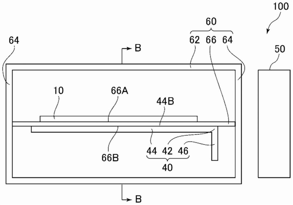
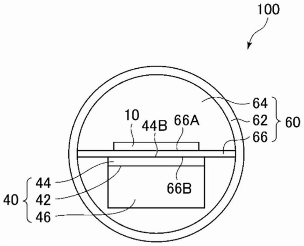
[0042] Below, refer to Figure 1A ~ Figure 4 The first embodiment will be described. First, refer to Figure 1A as well as Figure 1B The function and configuration of the light emitting device 100 of this embodiment will be described. Next, refer to image 3 The light emitting operation of the light emitting device 100 of this embodiment will be described. Next, effects of this embodiment will be described.
[0043]
[0044] The light emitting device 100 of the present embodiment has a function of emitting light by causing the light emitting substrate 10 to emit light. For example, the light emitting device 100 is used as a lighting device.
[0045] The light emitting device 100 includes a light emitting substrate 10, a flat heat pipe 40 (an example of a flat heat pipe mechanism), a cooling fan 50 (an example of a cooling unit), a case 60 (an example of a housing unit), a power supply (not shown), a switch (Illustration omitted).
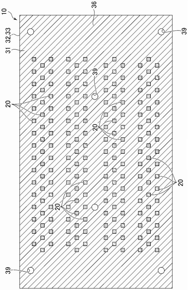
[0046] Here, the light emitting sub...
no. 2 Embodiment approach 》
[0141] Next, refer to Figure 5A as well as Figure 5B A second embodiment will be described. Hereinafter, only the present embodiment and the first embodiment (refer to Figure 1A , Figure 1B etc.) are explained in different parts.
[0142]
[0143] The light emitting device 100A of this embodiment has the light emitting device 100 of the first embodiment as a basic structure, and further includes a heat sink 70
[0144] Here, the heat sink 70 has a function of dissipating part of the heat taken away from the light emitting substrate 10 by the flat heat pipe 40 . The heat sink 70 is arranged on the side opposite to the light emitting substrate 10 across the flat heat pipe 40 , and is in contact with the first flat plate portion 44 of the flat heat pipe 40 . As an example, the fins 70 are composed of a plurality of plates, protrude in the plate thickness direction of the first flat plate portion 44 similarly to the second flat plate portion 46 , and are arranged along t...
no. 3 Embodiment approach 》
[0154] Next, refer to Figure 6A as well as Figure 6B A second embodiment will be described. Hereinafter, only the present embodiment and the second embodiment (refer to Figure 5A as well as Figure 5B etc.) are explained in different parts.
[0155]
[0156] Like the light emitting device 100A of the second embodiment, the light emitting device 100B of the present embodiment has the light emitting device 100 of the first embodiment as a basic configuration and further includes a heat sink 70 .
[0157] However, in the case of this embodiment, the posture of attaching the flat heat pipe 40 to the plate 66 is different from that of the second embodiment. Specifically, the flat heat pipe 40 of the present embodiment is attached to the plate 66 so that the second flat portion 46 is located on the side opposite to the side of the cooling fan 50 . Therefore, in the present embodiment, the heat sink 70 is disposed between the second flat plate portion 46 and the cooling fan...
PUM
| Property | Measurement | Unit |
|---|---|---|
| thickness | aaaaa | aaaaa |
| glass transition temperature | aaaaa | aaaaa |
| storage modulus | aaaaa | aaaaa |
Abstract
Description
Claims
Application Information
 - R&D Engineer
- R&D Manager
- IP Professional
- Industry Leading Data Capabilities
- Powerful AI technology
- Patent DNA Extraction
Browse by: Latest US Patents, China's latest patents, Technical Efficacy Thesaurus, Application Domain, Technology Topic.
© 2024 PatSnap. All rights reserved.Legal|Privacy policy|Modern Slavery Act Transparency Statement|Sitemap