
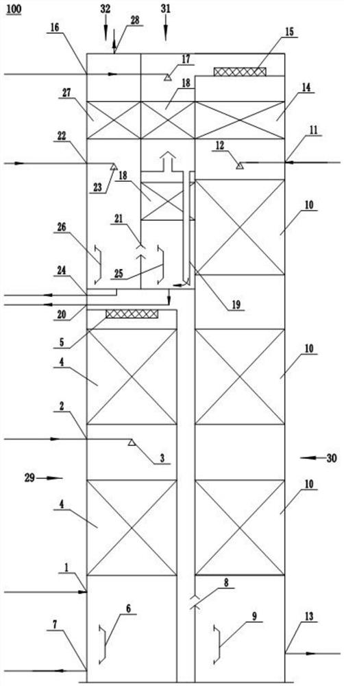
A low partial pressure carbon dioxide capture and absorption tower

A carbon dioxide and absorption tower technology, applied in the field of carbon dioxide emission reduction equipment, can solve the problems of unfavorable carbon dioxide capture system construction, long system process, high cost, and achieve the effect of reducing equipment investment, reducing construction land, and uniform gas-liquid distribution

Active Publication Date: 2022-08-02
CHINA PETROLEUM & CHEM CORP +2
View PDF8 Cites 0 Cited by
  • Summary
  • Abstract
  • Description
  • Claims
  • Application Information

AI Technical Summary

Problems solved by technology

[0002] Coal-fired power plants, cement kilns, steel plants, refineries and other enterprises have a large amount of low partial pressure carbon dioxide in the tail gas, which is the key area of ​​national carbon dioxide emission reduction. Considering factors such as carbon dioxide capture cost and technology maturity, currently The low partial pressure carbon dioxide capture system mostly adopts the chemical absorption method. Before the amine absorbent is used in the absorption tower to capture carbon dioxide, the raw material gas needs to be washed in the water washing tower, the temperature is controlled, and the solid particles, SO 2 , NOx and other harmful components. At the same time, it is necessary to control the amine escape and water balance of the capture system. The entire absorption reaction system needs to be equipped with raw material deep purification towers, absorption towers, scrubbers and other links. The system process is long, occupies a large area, and is expensive. , which is not conducive to the construction of large-scale carbon dioxide capture system

Method used


Image

  • A low partial pressure carbon dioxide capture and absorption tower

Examples


Embodiment Construction

[0030] The technical solutions in the embodiments of the present invention will be clearly and completely described below with reference to the accompanying drawings in the embodiments of the present invention. Obviously, the described embodiments are only a part of the embodiments of the present invention, rather than all the embodiments. Based on the embodiments of the present invention, all other embodiments obtained by those of ordinary skill in the art without creative efforts shall fall within the protection scope of the present invention.

[0031] The purpose of the present invention is to provide a low partial pressure carbon dioxide capture and absorption tower to solve the problems existing in the above-mentioned prior art, integrate flue gas purification, carbon dioxide absorption, and amine escape control, reduce floor space, and aim to provide large-scale The design and fabrication of low partial pressure carbon dioxide capture reactors provide a new way of thinkin...


PUM


Abstract

The invention discloses a low partial pressure carbon dioxide capture and absorption tower, which relates to the technical field of carbon dioxide emission reduction equipment. Structure; the primary scrubbing structure includes a flue gas inlet, a primary water inlet and a primary drain, the absorption structure includes a first amine escape control bed, a lean liquid inlet and a rich liquid outlet, and the secondary scrubbing structure includes a second amine escape Control bed, secondary water inlet and secondary drain, and the tertiary washing structure includes a third amine escape control bed, a tertiary water inlet, a tertiary drain and an exhaust gas outlet; the primary drain is connected to the primary water inlet, The tertiary water inlet is communicated, the secondary water outlet is communicated with the secondary water inlet, and the tertiary water outlet is communicated with the tertiary water inlet. The invention integrates flue gas purification, carbon dioxide absorption, and amine escape control, and reduces floor space.

Description

technical field [0001] The invention relates to the technical field of carbon dioxide emission reduction equipment, in particular to a low partial pressure carbon dioxide capture and absorption tower. Background technique [0002] There is a large amount of low partial pressure carbon dioxide in the exhaust gas emitted by coal-fired power plants, cement kilns, steel plants, refineries and other enterprises, which is the key area of ​​national carbon dioxide emission reduction. Considering factors such as carbon dioxide capture cost and technology maturity, currently The low partial pressure carbon dioxide capture system mostly adopts chemical absorption method. Before using amine absorbent to capture carbon dioxide in the absorption tower, it is necessary to wash the raw gas in the water washing tower to control the temperature, as well as the solid particles, SO 2 At the same time, it is necessary to control the amine escape and water balance of the capture system. The enti...

Claims


Application Information

Patent Timeline
Patent Type & Authority Patents(China)
IPC IPC(8): B01D53/62B01D53/78B01D53/96B01D53/60
CPCB01D53/62B01D53/78B01D53/96B01D53/60B01D2258/0283B01D2251/304B01D2251/604B01D2251/80B01D2257/504Y02A50/20
Inventor 李清方尚明华刘海丽王辉陆胤君王伟健
Owner CHINA PETROLEUM & CHEM CORP
Learn More