Variable-pipe-diameter flowmeter calibration device and calibration method

A technology of runoff and flowmeter, applied in the field of variable pipe diameter flowmeter calibration device, can solve the problems of scientific research work and industrial production, inconsistent real values, related result errors, etc., to reduce the workload of manual measurement and easy operation. , high precision effect

Active Publication Date: 2022-01-14
CHINA UNIV OF MINING & TECH
View PDF6 Cites 0 Cited by
  • Summary
  • Abstract
  • Description
  • Claims
  • Application Information

AI Technical Summary

Problems solved by technology

[0002] In many fields such as industrial production, scientific research and even daily life, measuring the gas flow in the pipeline is a frequently encountered and very important task. However, in the process of carrying out this work, one of the difficulties often encountered is: The diameter of the gas flow pipe does not match the diameter of the existing flowmeter tube
[0003] Since the gas is a compressible fluid, simply connecting the gas flow pipeline to be measured in series with the flowmeter measuring tube by changing the diameter will make the gas flow measured by the flowmeter "distorted", that is, the reading displayed by the flowmeter is consistent with the flow rate in the gas flow pipeline to be measured. The actual value of the gas flow rate is inconsistent, which will lead to errors in the related results of the subsequent application of the gas flow rate calculation, which will affect scientific research work and industrial production

Method used


Image

  • Variable-pipe-diameter flowmeter calibration device and calibration method
  • Variable-pipe-diameter flowmeter calibration device and calibration method
  • Variable-pipe-diameter flowmeter calibration device and calibration method

Examples


Embodiment 1

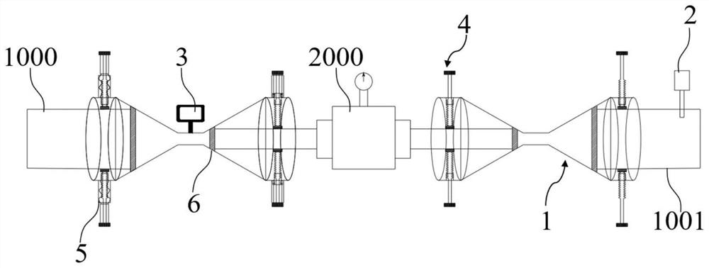
[0056]For the case where the diameter of the gas flow pipeline to be tested does not match the diameter of the flowmeter 2000 tube, simply connect the gas flow pipeline to be tested with the flowmeter 2000 tube to read the readings of the flowmeter 2000, because the gas is a compressible fluid , the gas flow value measured by the flowmeter 2000 at this time is inaccurate, which will lead to errors in the related results of subsequent application of gas flow measurement and calculation, which will affect scientific research work and industrial production. In view of this, this embodiment designs Disclosed is a calibrating device for a variable pipe diameter flowmeter.

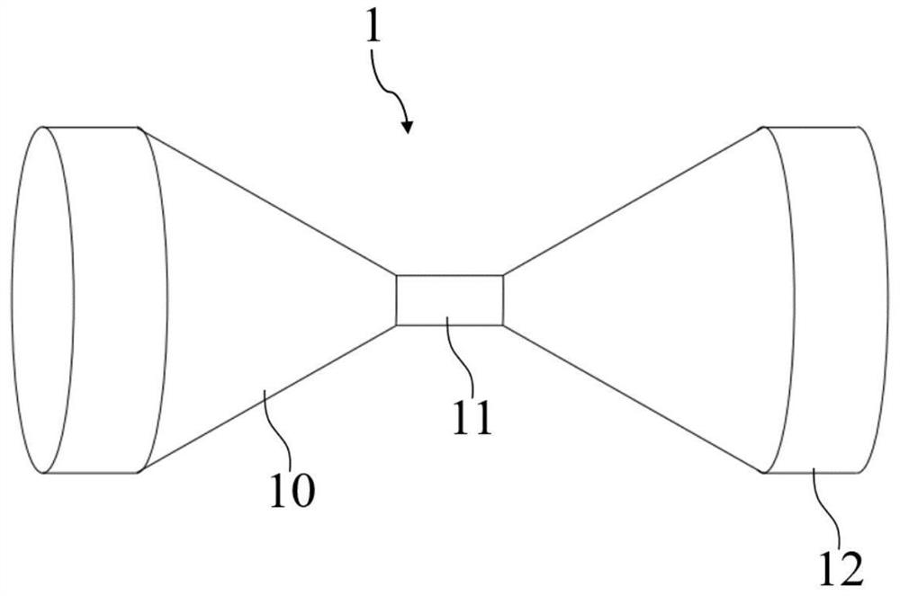
[0057] Such as figure 1 As shown, the flowmeter 2000 is usually connected to the middle of the airflow pipeline to be tested. There are measuring tubes at both ends of the flowmeter 2000, and the airflow pipeline to be tested is divided into the inlet airflow pipeline 1000 to be measured and the outlet airflow p...

Embodiment 2

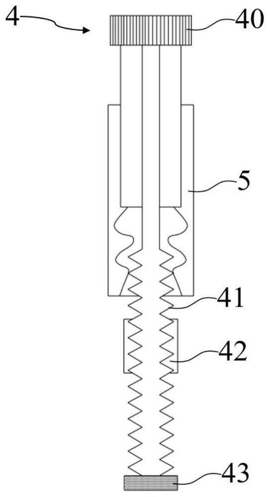
[0066] The variable pipe diameter flowmeter calibration device of this embodiment is further improved on the basis of Embodiment 1, and also includes a radial limiter 4, which passes through the double horn head sleeve 1 and along the double horn head sleeve 1 Set radially, the radial limiter 4 is arranged at both ends of the double horn head sleeve 1, respectively fixing the relative position of the air flow pipe to be measured and the double horn head sleeve 1 and the flowmeter 2000 measuring tube and the double horn head cover The relative position of cylinder 1.

[0067] In order to ensure the fixing of the airflow pipeline to be tested and the double horn head sleeve 1, and the reliable fixing of the flowmeter 2000 measuring tube and the double horn head sleeve 1, this embodiment designs a radial limiter 4 along the radial direction of the airflow pipeline to be tested. And flowmeter 2000 measuring tube for fixed limit.

[0068] Further, this embodiment shows a specific ...

Embodiment 3

[0077] The variable pipe diameter flowmeter calibration device of this embodiment is further improved on the basis of Embodiment 2, and also includes a radial depth sensor 5, which detects the outer pipe diameter of the gas flow pipeline to be measured and the outer pipe of the flowmeter 2000. path.

[0078] In this embodiment, a radial depth sensor 5 is provided to detect the outer diameter of the airflow pipeline to be measured and the outer diameter of the measuring tube of the flowmeter 2000, thereby conveniently measuring and calculating the diameter ratio R of the airflow pipeline to be measured and the measuring tube of the flowmeter 2000, simplifying Data information acquisition process before calibration.

[0079] Further, the radial depth sensor 5 is transmission-connected to the screw rod 41 of the radial limiter 4 , and the outer diameter of the gas flow pipeline to be measured and the outer diameter of the flow meter 2000 measuring tube are measured by detecting t...


PUM


Abstract

The invention discloses a calibration device and a calibration method for a variable-pipe-diameter flowmeter and belongs to the field of pipeline gas flow measurement. The device comprises an inlet to-be-measured airflow pipeline, an outlet to-be-measured airflow pipeline and a flow meter, and further comprises a double-trumpet-head sleeve, a viscometer and a signal processing digital display module, the double-trumpet-head sleeve is a barrel with trumpet-shaped openings in the two ends, and the to-be-measured airflow pipeline is coaxially communicated with a flowmeter measuring pipe through the double-trumpet-head sleeve; the viscometer is arranged at the inlet to-be-detected airflow pipeline or the outlet to-be-detected airflow pipeline and is used for detecting a kinematic viscosity coefficient of the to-be-detected airflow; the signal processing digital display module is used for correcting the data of the flow meter and displaying the corrected gas flow; and the signal processing digital display module is used for correcting and displaying the corrected real gas flow in the gas flow pipeline to be measured through a flow correction model according to the pipe diameter ratio, the reading of the flowmeter and the reading of the viscometer. The device is convenient to operate, high in universality and high in precision after final calibration, and flow calibration of to-be-measured gas flow pipelines and flowmeters with different gases and different pipe diameter ratios can be achieved.

Description

technical field [0001] The invention belongs to the technical field of pipeline gas flow measurement, and more specifically relates to a calibration device and a calibration method for a variable pipe diameter flowmeter. Background technique [0002] In many fields such as industrial production, scientific research and even daily life, measuring the gas flow in the pipeline is a frequently encountered and very important task. However, in the process of carrying out this work, one of the difficulties often encountered is: The diameter of the gas flow pipe does not match the diameter of the existing flowmeter tube. [0003] Since the gas is a compressible fluid, simply connecting the gas flow pipeline to be measured in series with the flowmeter measuring tube by changing the diameter will make the gas flow measured by the flowmeter "distorted", that is, the reading displayed by the flowmeter is consistent with the flow rate in the gas flow pipeline to be measured. The actual ...

Claims


Application Information

Patent Timeline
Patent Type & Authority Applications(China)
IPC IPC(8): G01F15/00G01F15/18G01F25/10
CPCG01F15/00G01F15/185
Inventor 朱金佗陈梦林何新建周福宝王亮施宇张玉东郝雅馨
Owner CHINA UNIV OF MINING & TECH
Why Eureka
Try Eureka