Anti-epidemic visual indoor air monitoring system

A technology for indoor air and monitoring systems, applied to measuring devices, analyzing gas mixtures, instruments, etc., can solve the problems of long construction period, difficult maintenance and repair, complicated wiring, etc., and achieve the effect of fast and convenient construction and avoiding difficult wiring

Pending Publication Date: 2022-01-14
广东森林大道医疗科技有限公司
View PDF0 Cites 0 Cited by
  • Summary
  • Abstract
  • Description
  • Claims
  • Application Information

AI Technical Summary

Problems solved by technology

[0003] For temporary anti-epidemic resettlement sites, the monitoring of the air in temporary resettlement rooms also requires good air circulation and basic air monitoring equipment and systems. For temporary anti-epidemic resettlement rooms, people usually live for several months to 10 months according to the needs of the epidemic. The time varies from several years, and the placement indoors is a high-risk area for the emergence of viruses. The best way to deal with viruses is to maintain indoor air circulation, so a device that monitors indoor air circulation is needed, and the spread of viruses is often accompanied by bacteria. Diffusion, so it is necessary to monitor the indoor planktonic bacteria. For the construction of the temporary device system, there is no need for too many and too complicated monitoring devices. It only needs to monitor whether the air is circulating, temperature and humidity, planktonic bacteria, etc. But the traditional hardware devices are all connected by wires. Since the resettlement room is temporarily built and has strong mobility, the wired method is not only complicated in wiring, but also has a long construction period and is difficult to maintain and repair. Therefore, it is necessary to A temporary visual indoor air monitoring system for anti-epidemic

Method used


Image

  • Anti-epidemic visual indoor air monitoring system
  • Anti-epidemic visual indoor air monitoring system

Examples


Embodiment Construction

[0015] The present invention will be described in detail below in conjunction with the accompanying drawings and specific embodiments. Obviously, the described embodiments are only a part of the embodiments of the application, not all of them. Based on the embodiments of the application, those of ordinary skill in the art All other embodiments obtained under the premise of no creative work belong to the scope of protection of this application.

[0016] In this embodiment, the present invention is specifically implemented according to the following steps:

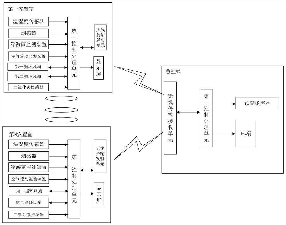
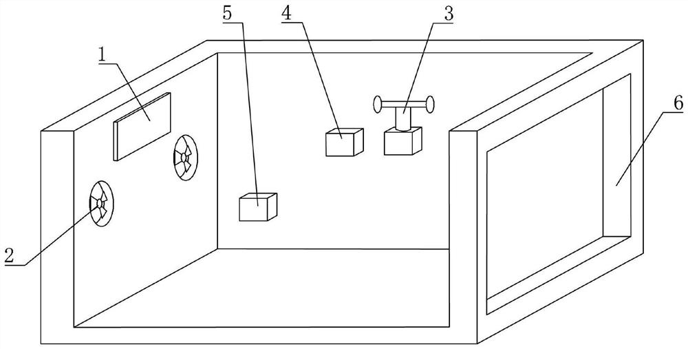
[0017] Such as Figure 1-2 As shown, it includes a plurality of anti-epidemic placement rooms, and a plurality of said placement rooms are wirelessly connected with a master control terminal. A single described placement room includes two circulation fans 2 embedded side by side on the side wall of the room, and installed with An air flow monitoring device 3 and a planktonic bacteria monitoring device 4 are installed side b...


PUM


Abstract

The invention relates to the technical field of air monitoring, in particular to an anti-epidemic visual indoor air monitoring system, which comprises a plurality of anti-epidemic placement rooms, the plurality of placement rooms are wirelessly connected with a master control end, and each placement room comprises two circulating fans which are embedded and mounted on one indoor side wall side by side; an air flow monitoring device and a planktonic bacteria monitoring device are installed on the side wall adjacent to the side wall where the circulating fan is installed side by side, and a temperature and humidity sensor, a smoke sensor and a carbon dioxide sensor are fixedly arranged on the indoor top plate. A display device is fixedly arranged above the circulating fan and comprises a display screen fixedly embedded in the display device and a first control processing unit installed in a shell of the display device. The circulating fan, the smoke detector, the planktonic bacteria monitoring device, the air flow monitoring device, the carbon dioxide sensor and the temperature and humidity sensor are all connected with the first control processing unit. The method has the advantages of being high in construction speed, free of wiring and high in flexibility.

Description

technical field [0001] The invention relates to the technical field of indoor air monitoring, in particular to an anti-epidemic visualized indoor air monitoring system. Background technique [0002] Air monitoring refers to the fixed-point, continuous or regular sampling and measurement of pollutants present in the air. In order to monitor the air, generally several air monitoring points are set up in a city, and automatic monitoring instruments are installed for continuous automatic monitoring. Air monitoring items mainly include sulfur dioxide, nitrogen monoxide, hydrocarbons, floating dust, etc. Air monitoring is the basis of air quality control and reasonable evaluation of air quality. [0003] For temporary anti-epidemic resettlement sites, the monitoring of the air in temporary resettlement rooms also requires good air circulation and basic air monitoring equipment and systems. For temporary anti-epidemic resettlement rooms, people usually live for several months to ...

Claims


Application Information

Patent Timeline
IPC IPC(8): G01N33/00
CPCG01N33/0004
Inventor 王嘉
Owner 广东森林大道医疗科技有限公司
Why Eureka
Try Eureka