Portable carbon resistance welding device

A welding device and a portable technology, applied in the direction of electric heating devices, auxiliary devices, welding equipment, etc., can solve the problems of reducing the convenience of welding devices, time-consuming and laborious operation, and the inconvenience of carrying welding tools, so as to reduce power outage maintenance time and save Working hours fee, the effect of protecting interests

Active Publication Date: 2022-01-21
STATE GRID SHANDONG ELECTRIC POWER
View PDF11 Cites 0 Cited by
  • Summary
  • Abstract
  • Description
  • Claims
  • Application Information

AI Technical Summary

Problems solved by technology

[0003] However, there are currently two main methods to solve copper-aluminum connection oxidation. One is to use copper-aluminum transition clamps and terminals; the other is to use cable ends and wire ends to be tinned. Aluminum transition clips and terminals", rarely use hot tin treatment, only the joints and connection points in indoor lighting circuits are often treated with hot tin
The hot tin treatment has an advantage, which can make the copper and aluminum wires tightly connected, and solve the problem of poor contact caused by the oxidation of copper and aluminum connections. It is limited when used in the field, and although it can be electrically connected to an external power supply through a wire, the operation process is time-consuming and laborious, and it is very inconvenient to carry welding tools, which leads to certain limitations in field soldering work, and the current welding device is under maintenance. When it is used, because the internal structure of the shell is usually fastened by a large number of bolts, it is not easy to disassemble, which reduces the convenience of welding device maintenance.

Method used


Image

  • Portable carbon resistance welding device
  • Portable carbon resistance welding device
  • Portable carbon resistance welding device

Examples


Embodiment

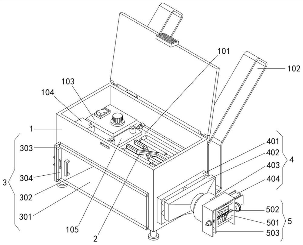
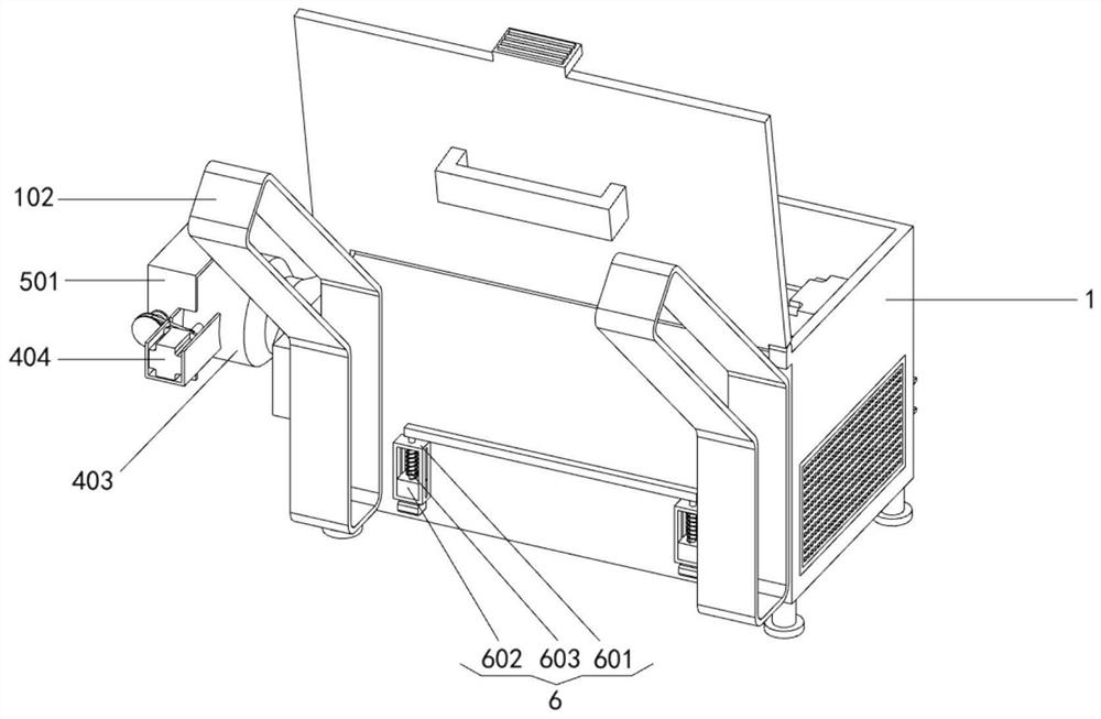
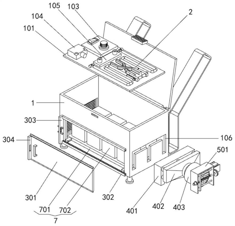
[0036] Example: Please refer to Figure 1 to Figure 10 :

[0037] The present invention proposes a portable carbon resistance welding device, comprising: a housing box 1; a rectangular opening is opened at the lower part of the front end of the housing box 1, and a shield assembly 3 is installed outside the rectangular opening on the front end of the housing box 1; The right end surface of the box body 1 is provided with an E-shaped port 106 for installing the blower cover A401, and the right end surface of the containing box body 1 is located at the E-shaped port 106. A blowing mechanism 4 is provided, and the right end of the blowing mechanism 4 is provided with a cleaning part 5. The rear end surface of the storage box 1 is equipped with a limiting part 6, and the inner bottom surface of the storage box 1 is equipped with a battery assembly 7, which is used to provide power for the hand-held welding piece 2; the inside of the storage box 1 is fixed with a support plate 101,...


PUM


Abstract

The invention provides a portable carbon resistance welding device, and relates to the technical field of welding devices. The portable carbon resistance welding device comprises an accommodating box body. A rectangular through opening is formed in the lower part of the front end face of the accommodating box body, and a shielding assembly is mounted in the position, outside the rectangular through opening, of the front end face of the accommodating box body; and an E-shaped through opening is formed in the right end face of the accommodating box body, an air blowing mechanism is arranged at the position, located at the E-shaped through opening, of the right end face of the accommodating box body, a cleaning part is arranged at the right end of the air blowing mechanism, and a limiting part is installed on the rear end face of the accommodating box body. Through the arrangement of the accommodating box body and a battery assembly, the welding device cannot be limited when being used outdoors; and through arrangement of the shielding assembly, a large number of bolts and other fasteners do not need to be disassembled through tools during maintenance of the welding device, so that the convenience during maintenance of the welding device is improved, and the problems that an existing welding device is limited during field use and is not easy to disassemble during maintenance, and convenience during maintenance is lowered are solved.

Description

technical field [0001] The invention relates to the technical field of welding devices, in particular to a portable carbon resistance welding device. Background technique [0002] With the country's line transformation of urban and rural power grids, the power distribution outgoing cables, household lines, household lines and agricultural irrigation lines on the lines have been changed from the original overhead lines to buried cables. In the distribution network lines, whether it is a high-voltage line or a low-voltage line, it is a mixed material line of aluminum and copper lines. Because the copper-aluminum connection is easy to heat, corrode, and disconnect at the connection point, the power supply line will appear. Electrical faults such as phase failure, short circuit, and power outage bring inconvenience to the production and life of residents. In order to avoid line faults and ensure reliable power supply, it is necessary to solve the problem of distribution network...

Claims


Application Information

Patent Timeline
Patent Type & Authority Applications(China)
IPC IPC(8): B23K3/00B23K3/047B23K3/08
CPCB23K3/00B23K3/0471B23K3/08Y02E60/10
Inventor 杨平马劲松吕峰杨光刘刚高瑾
Owner STATE GRID SHANDONG ELECTRIC POWER
Why Eureka
Try Eureka