
Ecological buffer zone for vertical revetment

A buffer belt and ecological technology, applied in the application, bank pier, bank wall, etc., can solve the problems of cumbersome operation process, no protection mechanism, water wave damage, etc., to achieve the effect of simple operation process, normal growth, and convenient installation.

Inactive Publication Date: 2022-01-21
杭州绿益环境科技有限公司
View PDF0 Cites 2 Cited by
  • Summary
  • Abstract
  • Description
  • Claims
  • Application Information

AI Technical Summary

Problems solved by technology

[0003] In order to effectively control non-point source pollution, an ecological buffer zone is usually used for treatment, but the current ecological buffer zone still has certain deficiencies. For example, most of the ecological floating island mechanisms used in the existing ecological buffer zone have inconvenient splicing The disadvantages are that the operation process is cumbersome and inconvenient to use, and there is no protective mechanism on the existing ecological floating island mechanism, which makes the aquatic plants on the ecological floating island mechanism prone to dumping, and is easily damaged by water waves, thereby affecting In addition, most of the existing ecological buffer zones only have ecological floating island structures, which leads to incomplete purification of non-point source pollution. Therefore, we propose an ecological buffer zone for vertical revetment to solve the above problems

Method used


Image

  • Ecological buffer zone for vertical revetment
  • Ecological buffer zone for vertical revetment
  • Ecological buffer zone for vertical revetment

Examples


Embodiment

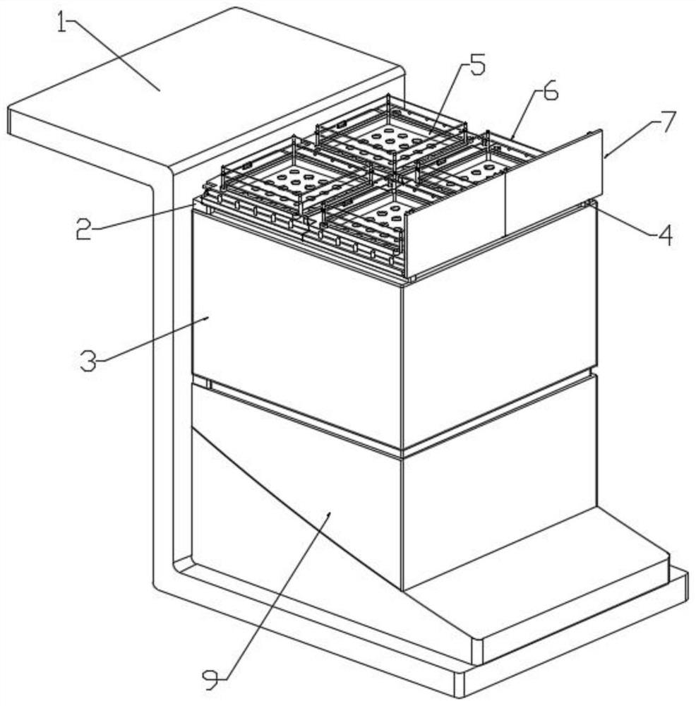
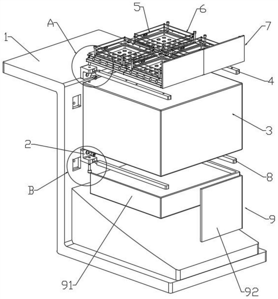
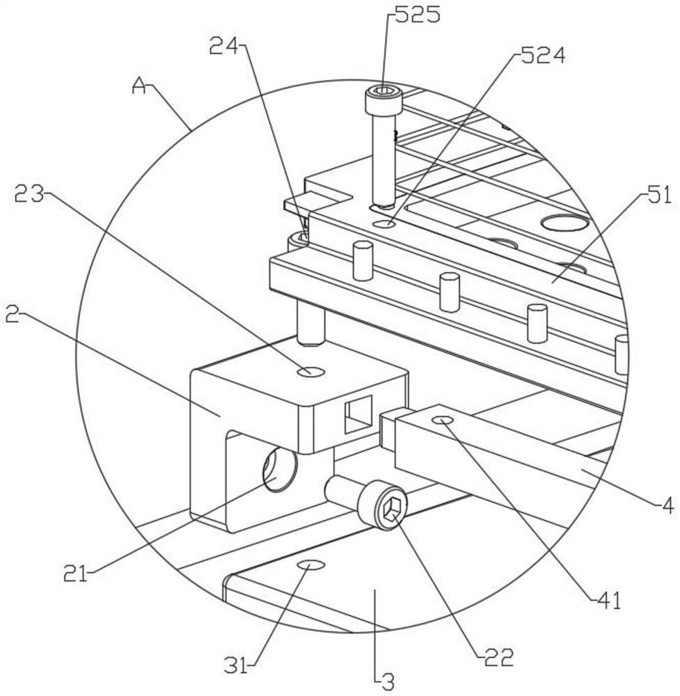
[0032] Example: such as Figure 1 to Figure 10As shown, the present invention provides a kind of ecological buffer belt for vertical bank revetment, comprising a bumper 1, on which a fixed rod 2 is detachably arranged on the bumper 1, and a net cage is detachably arranged between the fixed rods 2 Filter material 3, the net cage filter material 3 is composed of a net cage shell and a biological filter material, and the biological filter material is composed of one or more combinations of activated carbon, ceramsite, MBBR filler, and ball filler, so as to be able to face the source Pollution plays a good role in purification. The fixed rod 2 near the upper end of the barge 1 is fixedly inserted with the first inner rod 4, and the first inner rod 4 is detachably provided with an ecological floating island mechanism 5, and the corresponding The adjacent ecological floating island mechanisms 5 are engaged with each other, and the ecological floating island mechanism 5 is provided w...


PUM


Abstract

The invention discloses an ecological buffer zone for a vertical revetment, and belongs to the technical field of water pollution abatement. The ecological buffer zone comprises a barge ridge, fixing rods are detachably arranged on the barge ridge, net cage filter materials are detachably arranged between the fixing rods, and a first inner rod is fixedly inserted in the fixing rod close to the upper end of the barge ridge. Clamping plates on one set of frame bodies are aligned with clamping grooves in the other frame body and pressed downwards, then the corresponding wedge-shaped blocks move in the opposite directions and are stored in first cavities, at the moment, first springs are compressed, when the clamping plates are completely clamped into the clamping grooves, the first springs stretch, so that the wedge-shaped blocks are driven to move in the opposite directions, and the wedge-shaped blocks are driven to be inserted into the corresponding wedge-shaped grooves. According to the ecological buffer zone for the vertical revetment, a spliced ecological floating island mechanism can be held by hand, the upper connecting plate of the spliced ecological floating island mechanism is aligned with the lower connecting plate of another spliced ecological floating island mechanism, then the spliced ecological floating island mechanism can be pressed downwards until an inserting rod is inserted into the corresponding inserting hole, so that the quick splicing of the ecological floating island mechanism is realized, the operation process is simple, and the use is convenient.

Description

technical field [0001] The invention relates to the technical field of water body pollution control, in particular to an ecological buffer zone for vertical revetment. Background technique [0002] Non-point source pollution, also known as non-point source pollution, is mainly composed of soil sediment particles, nutrients such as nitrogen and phosphorus, pesticides, and various atmospheric particles, which enter water, soil, or the atmosphere through surface runoff and farmland drainage. It has the characteristics of randomness, ambiguity and hysteresis. [0003] In order to effectively control non-point source pollution, an ecological buffer zone is usually used for treatment, but the current ecological buffer zone still has certain deficiencies. For example, most of the ecological floating island mechanisms used in the existing ecological buffer zone have inconvenient splicing The disadvantages are that the operation process is cumbersome and inconvenient to use, and the...

Claims


Application Information

Patent Timeline
IPC IPC(8): E02B3/06E02D5/76A01G31/02C02F9/14
CPCE02B3/066E02D5/76A01G31/02C02F3/32C02F1/001Y02P60/21
Inventor 叶诺刘阳闫磊曹伟贾中原何继华
Owner 杭州绿益环境科技有限公司
Learn More