Plasma tube with built-in resistor

A plasma tube and resistor technology, applied in the field of ion tubes, can solve problems such as failure of high-voltage oscillating lines to vibrate, decrease in product performance, and poor user experience. Reduced effect

Pending Publication Date: 2022-01-21
SHANGHAI YIZHONG ENVIRONMENTAL SCI & TECH DEV CO LTD
View PDF0 Cites 0 Cited by
  • Summary
  • Abstract
  • Description
  • Claims
  • Application Information

AI Technical Summary

Problems solved by technology

[0002] With the improvement of people's living standards, the degree of attention to hygiene and health is also increasing, and products such as air humidifiers, negative oxygen ion generators and air purifiers for home use have also emerged as the times require. These products are related to the rapid development of plasma technology. The development is inseparable. Most of the plasma tubes in the prior art are a form of dielectric discharge formed by the combination of inductance and capacitance. The problem is that when encountering an environment with high humidity and low temperature, especially central air-conditioning refrigeration When the air outlet is under normal conditions, the humidity of the air conditioner is relatively high, and the water molecules in the air and the air conditioner will be adsorbed to the surface of the ceramic tube and the quartz glass tube, causing the load current to increase, resulting in the failure of the high-voltage oscillating line to vibrate, and the performance of the product is reduced. How to solve the problem of how to solve the normal operation of the plasma tube in the environment of high humidity and low temperature is an urgent problem

Method used


Image

  • Plasma tube with built-in resistor
  • Plasma tube with built-in resistor
  • Plasma tube with built-in resistor

Examples


Embodiment Construction

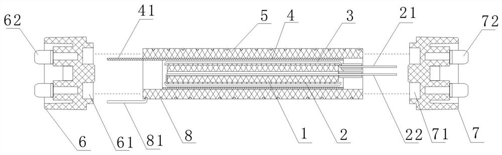
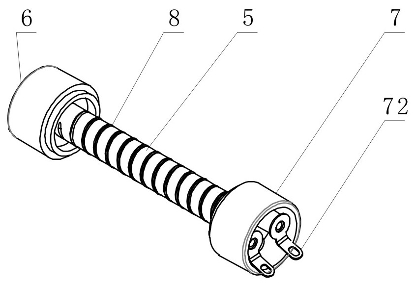
[0028] refer to figure 1 , figure 2 , the present invention includes a heating ceramic tube 1, a heating wire 2, a heat-shrinkable insulating sleeve 3, a stainless steel cylinder 4, an externally threaded ceramic tube 5, a high-voltage joint 6, a low-pressure joint 7 and a tungsten wire 8;

[0029] The heating ceramic tube 1 is a pipe fitting:

[0030] The heating wire 2 is wound by a metal wire into a spiral tube shape, one end of the spiral tube on the heating wire 2) leads to the first electrode 21, and the other end of the spiral tube leads to the second electrode 22;

[0031] The stainless steel cylinder 4 is a cylindrical part formed by curling a thin sheet, and the third electrode 41 is drawn from the thin sheet;

[0032] The externally threaded ceramic pipe 5 is a pipe fitting with a spiral groove on the outer surface;

[0033] The high-voltage joint 6 is in the shape of a circular platform, on which a first socket 61 and two high-voltage electrode pins 62 are arra...


PUM


Abstract

The invention discloses a plasma tube with a built-in resistor. The plasma tube is characterized in that an electric heating wire is wound on the outer side of a heating ceramic tube, and the outer side of the electric heating wire and the outer side of the heating ceramic tube are wrapped with a thermal shrinkage insulating bushing through a thermal shrinkage technology to form a resistor assembly; a tungsten filament is wound on the spiral groove of an external threaded ceramic tube, and a stainless steel cylinder which is curled into a cylinder shape is attached to the inner wall of the external threaded ceramic tube to form an ion tube assembly; and the resistor assembly is arranged in the ion tube assembly to form the plasma tube with the built-in resistor. According to the invention, during working, the plasma tube is matched with a direct-current power supply and a high-voltage oscillation circuit for use; the heat energy of the resistor assembly removes water mist on the surface of the ion tube assembly so as to greatly reduce the oscillation starting load of the high-voltage oscillation circuit, and when the medium discharges, the heat energy emitted by the resistor assembly plays a role in promoting the discharge of the medium; and the plasma tube has the advantages of being simple in structure, convenient to use, wide in application range and high in working efficiency.

Description

technical field [0001] The invention relates to the field of plasma technology, in particular to a plasma tube with built-in resistance. Background technique [0002] With the improvement of people's living standards, the degree of attention to hygiene and health is also increasing, and products such as air humidifiers, negative oxygen ion generators and air purifiers for home use have also emerged as the times require. These products are related to the rapid development of plasma technology. The development is inseparable. Most of the plasma tubes in the prior art are a form of dielectric discharge formed by the combination of inductance and capacitance. The problem is that when encountering an environment with high humidity and low temperature, especially central air-conditioning refrigeration When the air outlet is under normal conditions, the humidity of the air conditioner is relatively high, and the water molecules in the air and the air conditioner will be adsorbed to...

Claims


Application Information

Patent Timeline
Patent Type & Authority Applications(China)
IPC IPC(8): H05H1/24F24F6/10
CPCH05H1/24F24F6/10
Inventor 孙伟忠
Owner SHANGHAI YIZHONG ENVIRONMENTAL SCI & TECH DEV CO LTD
Why Eureka
Try Eureka