
Preparation process of rigid-flex board with laser blind holes

A soft-rigid combination board and preparation technology, which is applied in multi-layer circuit manufacturing, printed circuit manufacturing, electrical components, etc., can solve the problems of difficult production, many materials and manpower, and various production processes, so as to improve efficiency and precision, The effect of short process flow

Pending Publication Date: 2022-01-21
恒赫鼎富(苏州)电子有限公司
View PDF0 Cites 0 Cited by
  • Summary
  • Abstract
  • Description
  • Claims
  • Application Information

AI Technical Summary

Problems solved by technology

[0003] However, due to the various production processes of the rigid-flex board, it also has problems such as high production difficulty, low yield rate, more materials and manpower, especially the blind hole design of the rigid-flex board is increasing. The precision requirements of the holes are getting higher and higher. Using the traditional etching method on the copper foil to open the window and then process the blind hole, not only the precision is low, but also the process is longer and the production cost is higher.

Method used


Image

  • Preparation process of rigid-flex board with laser blind holes
  • Preparation process of rigid-flex board with laser blind holes
  • Preparation process of rigid-flex board with laser blind holes

Examples


Embodiment 1

[0024] The preparation process of a rigid-flex board with laser blind holes provided by the present invention comprises the following steps:

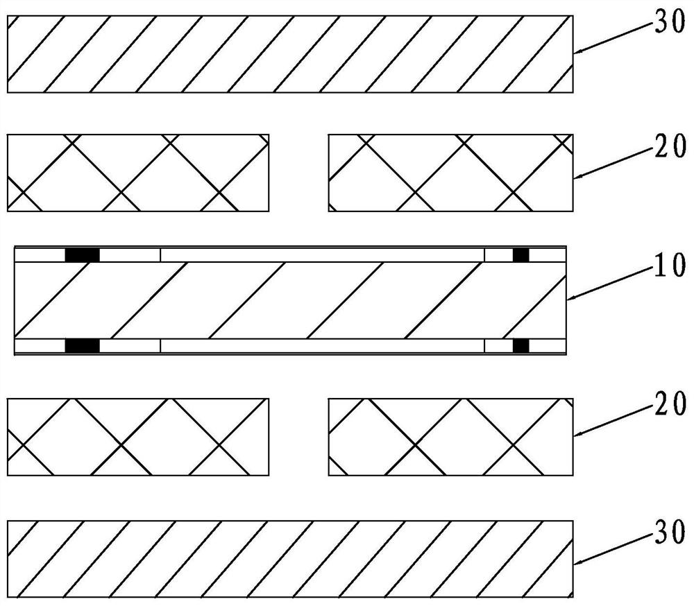
[0025] S1. Provide the flexible board 10 as the inner layer, and pre-make the circuit on the flexible board 10 and paste the cover film; provide the PP board 20 as the interlayer, and laser out the relief holes, openings and positioning holes on the PP board 20 , and, drilling and punching openings on the PP board 20; providing the copper foil 30 as the outer circuit, and drilling a relief hole and a positioning hole on the copper foil 30;

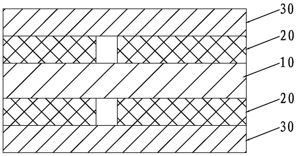
[0026] S2. Based on step S1, copper foil 30, PP board 20, soft board 10, PP board 20 and copper foil 30 are figure 1 The sequence shown is stacked sequentially and then pressure-transmitted and stacked, such as figure 2 shown;

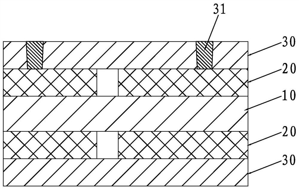
[0027] S3. Based on step S2, using the optical point of the inner flexible board 10 as a reference point, the pure copper laser is burned off by laser at the position whe...

Embodiment 2

[0031] Based on Example 1, in this Example 2, in step S3, the double-sided copper foil 30 is simultaneously laser-processed to form a primary blind hole 31; and in step S4, the double-sided PP board 20 is simultaneously laser-processed to form a secondary Blind hole 21.

[0032] The present invention uses a laser method to burn off the pure copper that needs laser blind holes to replace the traditional etching and window opening method in which copper is etched away at the blind holes. It has a short process flow, can effectively reduce costs and laser processing The advantages of high precision greatly improve the efficiency and precision of blind hole processing.


PUM


Abstract

The invention discloses a preparation process of a rigid-flex board with laser blind holes. The preparation process comprises the following steps: S1, providing a flexible board serving as an inner layer, a PP board serving as an interlayer and a copper foil serving as an outer layer circuit; S2, stacking the copper foil, the PP board, the soft board, the PP board and the copper foil in sequence to be subjected to pressure transmission lamination; S3, taking an optical point of the inner-layer soft board as a reference point, and burning off pure copper in a laser mode at a position where a blind hole needs to be processed to form a first-stage blind hole; S4, taking an optical point of the inner-layer soft board as a reference point, and burning off PP laser at the position of the first-stage blind hole in a laser mode to form a second-stage blind hole, so as to form a blind hole needing to be processed; and S5, cleaning and checking the blind hole. According to the invention, the manufacturing mode that pure copper at the blind hole position needing laser is burnt out in a laser mode is used for replacing a traditional etching windowing mode that copper is etched away at the blind hole position through etching, and the method has the advantages of being short in technological process, capable of effectively reducing cost, high in laser machining precision and the like.

Description

technical field [0001] The invention relates to the technical field of production of rigid-flex boards, in particular to a preparation process of rigid-flex boards with laser blind holes. Background technique [0002] Rigid-flex board is a circuit board with FPC characteristics and PCB characteristics formed by combining flexible circuit boards and rigid circuit boards through lamination and other processes according to relevant process requirements. Since the rigid-flex board has both the characteristics of FPC and PCB, it can be used in some products with special requirements. It has both a certain flexible area and a certain rigid area, which is helpful for saving the internal space of the product and reducing the It is of great help to increase the volume of the finished product and improve the performance of the product. [0003] However, due to the various production processes of the rigid-flex board, it also has problems such as high production difficulty, low yield ...

Claims


Application Information

Patent Timeline
Patent Type & Authority Applications(China)
IPC IPC(8): H05K3/46
CPCH05K3/4691
Inventor 石可义
Owner 恒赫鼎富(苏州)电子有限公司
Learn More