Circular truncated cone type efficient dry-type magnetic separation device
A magnetic separation device, desktop technology, applied in the direction of magnetic separation, solid separation, chemical instruments and methods, etc., can solve the problems of inability to effectively deal with the agglomeration of fine-grained materials and the inability to obtain the separation effect, so as to improve the efficiency of magnetic separation , expand applications, improve the quality of the effect
- Summary
- Abstract
- Description
- Claims
- Application Information
AI Technical Summary
Problems solved by technology
Method used
Image
Examples
Embodiment 1
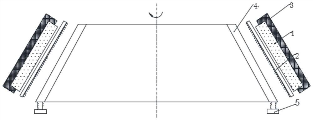
[0048] see figure 1 , 4 As shown, as the basic structure of the present invention, the round table type high-efficiency dry magnetic separation device of the present invention includes a magnetic system 1 , a rotating magnetic medium 2 , a yoke 3 , a fluidization device 4 and a bracket 5 . The space between the rotating magnetic medium 2 and the fluidization device 4 is the sorting domain, the magnetic system 1 is a fixed magnetic system, and is located outside the rotating magnetic medium 2, that is, outside the sorting domain, and the yoke 3 is wrapped in the magnetic Outside of Department 1. The upper side of the sorting area is provided with a material inlet, and the lower side is provided with a fine material bin, a middle material bin and a tail material bin. The inside of the rotating magnetic medium 2 is provided with a protrusion of a magnetically permeable material that induces a high gradient magnetic field. The fluidization device 4 is externally connected with ...
Embodiment 2
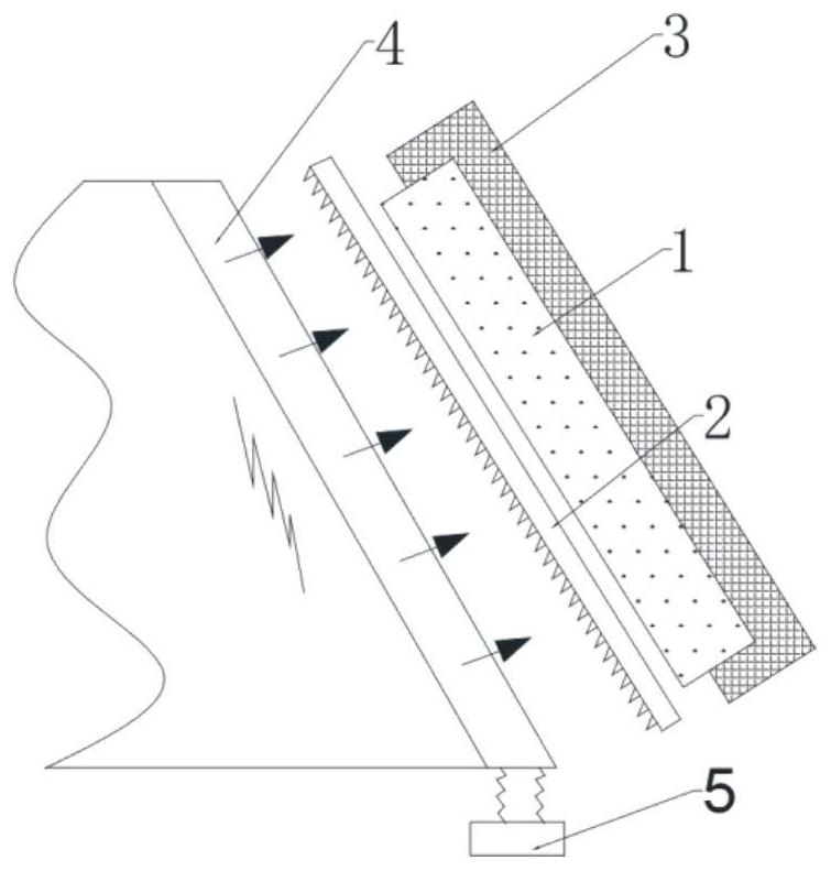
[0052] see figure 2 and Figure 4 As shown, the enhanced air flow field is intervened alone, and the fluidization device 4 is connected to the air supply device. The fluidization device 4 is a conical air cavity or a conical annular air cavity, and the outer surface of the fluidization device 4 is a porous air distribution device. plate. The air supply device provides fluid to the air chamber of the fluidization device 4, and then disperses it into the sorting area through the porous air distribution plate, such as figure 2indicated by the arrow in . The angle of the side of the round table is greater than the accumulation angle of the material to avoid the accumulation of the material in the separation area under the condition of no air flow. Due to the absence of vibration, the interlayer thickness of the sorting domain can be further reduced. This design scheme has a simple and compact structure. The enhanced air flow not only loosens the materials on the surface of t...
Embodiment 3
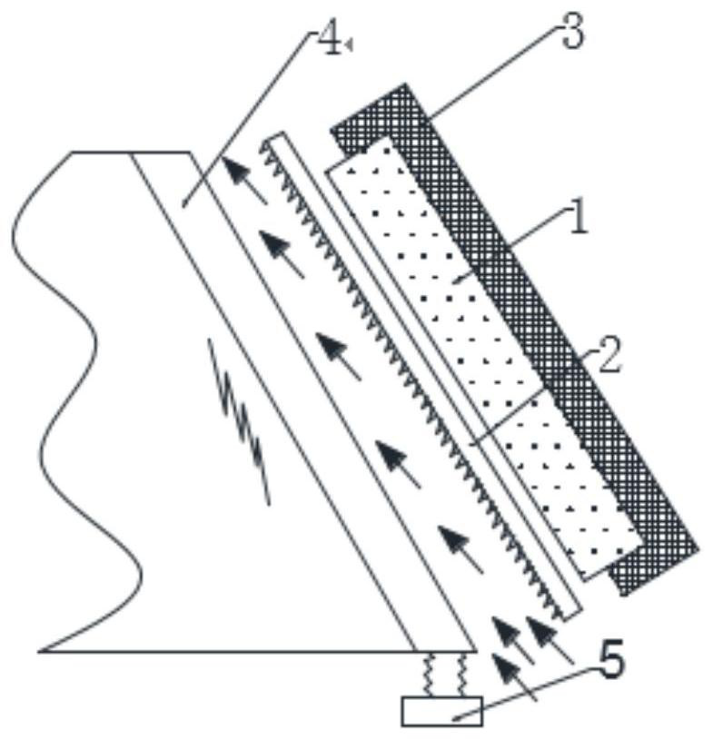
[0054] see image 3 As shown, the enhanced air flow field is intervened alone, but the fluidization device 4 does not need an external air supply device, but is a truncated circular thin plate as in Embodiment 1. The airflow moves upwards through the lower side of the sorting zone. Under the action of the airflow, the material enters the sorting zone and is in a loose state. Among them, the fine-grained non-magnetic materials directly move upward with the airflow and leave the sorting zone. Coarse grains and some fine grains are non-magnetic. The material can continue to move downward and enter the tailing bin; after the competition of magnetic force, gravity and fluid drag, the fine-grained magnetic material moves upward and leaves the sorting area, and part of it is adsorbed on the rotating magnetic medium 2, and the coarse-grained and The fine-grained magnetic material can be smoothly absorbed by the rotating magnetic medium 2 . This design scheme first removes part of the...
PUM
 Abstract
Description
Claims
Application Information
 - R&D Engineer
- R&D Manager
- IP Professional
- Industry Leading Data Capabilities
- Powerful AI technology
- Patent DNA Extraction
Browse by: Latest US Patents, China's latest patents, Technical Efficacy Thesaurus, Application Domain, Technology Topic, Popular Technical Reports.
© 2024 PatSnap. All rights reserved.Legal|Privacy policy|Modern Slavery Act Transparency Statement|Sitemap|About US| Contact US: help@patsnap.com


