Loop heat pipe solar heat collection system capable of emptying low-temperature water
A technology of solar heat collection and loop heat pipe, which is applied in the field of solar energy, can solve the problems of inability to realize remote control and low degree of intelligence, and achieve the effects of increasing vibration range, improving heat collection effect, and optimizing heating efficiency
- Summary
- Abstract
- Description
- Claims
- Application Information
AI Technical Summary
Problems solved by technology
Method used
Image

Examples
Embodiment 1
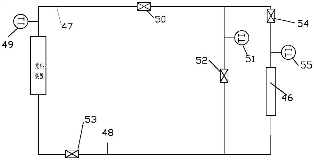
[0050] As an improvement, the central controller automatically controls the opening and closing of the valves 52 and 54 according to the detected temperature of the heat storage material and the temperature of the fluid entering the heat storage.
[0051] Preferably, valve 54 is open and valve 52 is closed during normal operation.
[0052] If the temperature of the heat storage material is higher than the temperature of the fluid entering the heat accumulator, the central controller automatically controls the valve 54 to close and the valve 52 to open simultaneously. Ensure that the fluid does not enter the heat accumulator, because if the fluid enters the heat accumulator 46 at this time, it will not only fail to achieve the effect of heat storage, but will transfer the heat in the heat storage material to the fluid, thereby reducing the heat storage effect. Energy can thus be saved by this measure.
[0053] If the temperature of the fluid detected by the bypass pipeline tem...
Embodiment 2
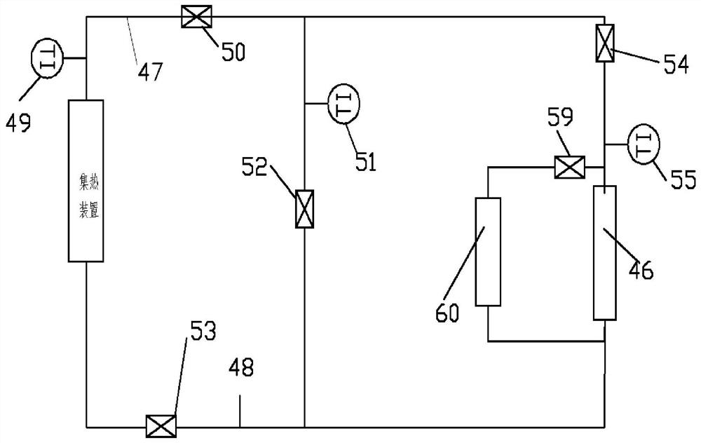
[0060] As an improvement, a power device, such as a pump or fan, is provided on the pipeline of the heat accumulator to drive the fluid; a discharge port is provided on the bypass pipeline to discharge the fluid, and a valve is provided at the discharge port; the central control The device automatically controls the opening and closing of the valves 50, 52, 54 according to the detected temperature of the inlet pipe of the heat accumulator 46, the temperature in the heat collector and the temperature of the bypass pipeline.
[0061] If the temperature of the inlet pipe of the heat accumulator detected by the central controller is lower than the temperature of the heat storage material of the heat accumulator, the central controller automatically closes the valve 50, opens the outlet valve, and starts the power plant to run at the same time. The fluid on the pipeline that does not meet the temperature requirements is discharged through the outlet of the bypass pipeline. After the...
Embodiment 3
[0071] Embodiment 3 is a further improvement of Embodiment 2.
[0072] If the temperature of the inlet pipe of the heat accumulator detected by the central controller is lower than the temperature of the heat storage material of the heat accumulator, the central controller automatically closes the valve 50, opens the outlet valve, and starts the power plant to run at the same time. The fluid on the pipeline that does not meet the temperature requirements is discharged through the outlet of the bypass pipeline. After the power unit runs for a certain period of time, close the valve at the outlet of the power unit; when the temperature of the fluid in the heat collector exceeds a certain value of the temperature of the heat storage material, Preferably above 5 degrees Celsius, valve 50 is opened, valve 54 is closed, and the fluid flows through the bypass pipeline. The pipeline valve 52 is closed, and the heat accumulator pipeline valve 54 is opened, so that the fluid enters the ...
PUM
 Abstract
Description
Claims
Application Information
PatSnap Eureka turns technology decisions into work you can execute. Powered by our Innovation Knowledge Graph, it runs expert workflows across engineering, life sciences, materials and intellectual property. Get your review-ready output in minutes.


