
Real-time monitoring and management system for abnormal vital signs of patient

A technology for vital signs and real-time monitoring, applied in patient-specific data, cardiac catheterization, vascular assessment, etc., can solve problems such as inability to respond to patient emergencies, increase patient risk, etc., to improve service life, improve efficiency, and ensure safety. Effect

Pending Publication Date: 2022-01-28
韩雪峰
View PDF1 Cites 0 Cited by
  • Summary
  • Abstract
  • Description
  • Claims
  • Application Information

AI Technical Summary

Problems solved by technology

[0004] A vital sign monitoring system in the above-mentioned patent has the following disadvantages: it cannot respond to possible emergencies of the patient during the monitoring process, which increases the risk of the patient

Method used


Image

  • Real-time monitoring and management system for abnormal vital signs of patient

Examples


Embodiment 1

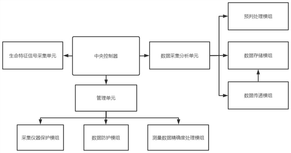
[0027] A real-time monitoring and management system for abnormal vital signs of patients, such as figure 1 As shown, it includes a central controller, a vital sign signal acquisition unit, and a data acquisition and analysis unit. Both the vital sign signal acquisition unit and the data acquisition and analysis unit are electrically connected to the central controller, and the vital sign signal acquisition unit is connected to the central controller. The data of various body function indexes in the treatment process of the patient is collected; the data collection and analysis unit includes a data transmission module, a data storage module and a pre-judgment processing module, and the data transmission module is used to monitor the required sensor The linearity and signal sensitivity are balanced to speed up and optimize the entire monitoring process. The data storage module uniformly summarizes the data monitored by the monitoring sensors, and the pre-judgment processing modul...

Embodiment 2

[0035] A real-time monitoring and management system for abnormal vital signs of patients, such as figure 1 As shown, the central controller is electrically connected with a management unit, and the management unit includes a collection instrument protection module, a data protection module, and a measurement data accuracy processing module. The management unit is used to monitor the vital sign signal collection unit and Data acquisition and analysis unit for management and protection.

[0036] The collection instrument protection module is used for overload protection of the blood sample saturation collection module, body temperature collection module, ECG collection module, heart rate collection module and blood pressure collection module. The standby power supply is enabled, and the interfaces of each data sensor are arranged reasonably and distinguished by different colors to facilitate the use of medical staff and patients.

[0037] The data protection module is used for ...


PUM


Abstract

The invention discloses a real-time monitoring and management system for abnormal vital signs of a patient, and relates to the technical field of real-time monitoring and management of vital signs of patients. The invention aims to improve the real-time monitoring efficiency of vital signs of a patient. The system specifically comprises a central controller, a vital sign signal acquisition unit and a data acquisition and analysis unit; the vital sign signal acquisition unit and the data acquisition and analysis unit are electrically connected with the central controller; the vital sign signal acquisition unit is used for acquiring various body function index data of a patient in a treatment process; and the data acquisition and analysis unit comprises a data transmission module, a data storage module and a pre-judgment processing module. Through the vital sign signal acquisition unit, the blood sample saturation acquisition module, the body temperature acquisition module, the electrocardio acquisition module, the heart rate acquisition module and the blood pressure acquisition module can be in direct contact with the skin surface of a patient, so that 24-hour uninterrupted monitoring of the patient can be realized.

Description

technical field [0001] The invention relates to the technical field of real-time monitoring and management of vital signs of patients, in particular to a real-time monitoring and management system for abnormal vital signs of patients. Background technique [0002] With the expansion of hospital scale and the gradual improvement of informatization, how to coordinate the development of Internet medical treatment and in-hospital treatment, innovate the mode of medical service, and comprehensively improve the service ability and level of medical and health institutions have become new problems faced by hospitals. The hospital information system is playing an increasingly important role. China is already an aging society. The medical needs of the huge elderly population have increased sharply, and the market demand capacity is huge. Therefore, it is necessary to study a real-time monitoring and management system for abnormal vital signs of patients. It can be widely used in the f...

Claims


Application Information

Patent Timeline
Patent Type & Authority Applications(China)
IPC IPC(8): A61B5/0205A61B5/00G16H10/60G16H50/70A61B5/145A61B5/318
CPCA61B5/02055A61B5/002G16H10/60G16H50/70A61B5/021A61B5/024A61B5/318A61B5/14542
Inventor 韩雪峰胡雪婵
Owner 韩雪峰
Learn More