Industrial robot capable of adjusting grabbing force and using method of industrial robot

An industrial robot and adjustable technology, applied in the field of robots, can solve the problems of falling clamping force, large device, damage, etc., and achieve the effect of increasing friction

Inactive Publication Date: 2022-01-28
南京付联微网络科技有限公司
View PDF0 Cites 1 Cited by
  • Summary
  • Abstract
  • Description
  • Claims
  • Application Information

AI Technical Summary

Problems solved by technology

[0002] Today, as automation is getting higher and higher, human handling has gradually disappeared in factories, replaced by robotic arms and manipulators. Although robotic arms and manipulators do not need to rest, their work efficiency is very efficient, and they can replace manual work in harsh environments. However, traditional robotic arms and manipulators only achieve the best results on objects of a fixed shape and size, or grip different solid objects, but it is difficult for the robotic arm and manipulator to grasp the gripping force during the gripping process. During the clamping process, it is easy to cause damage to the device due to falling or excessive clamping force. Therefore, it is necessary to design an industrial robot that can adjust the grasping force

Method used


Image

  • Industrial robot capable of adjusting grabbing force and using method of industrial robot
  • Industrial robot capable of adjusting grabbing force and using method of industrial robot
  • Industrial robot capable of adjusting grabbing force and using method of industrial robot

Examples


Embodiment 1

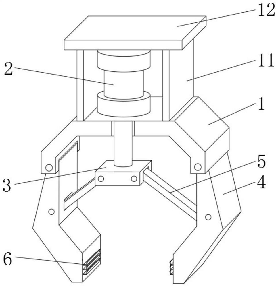
[0033] see Figure 1-2 , this embodiment provides an industrial robot with adjustable grasping strength, including a mounting base 1 and a cylinder 2 fixedly installed on the mounting base 1, and the two ends of the mounting base 1 are respectively provided with mounting grooves with the notches facing downwards. In the installation grooves at both ends of the mounting base 1, the clamping jaws 4 are rotated by rotating the pin shaft, so that the clamping jaws 4 can rotate around the two ends of the mounting base 1, and the output end of the cylinder 2 runs through the mounting base 1 and is fixedly connected with the connecting plate 3 , both ends of the connecting plate 3 are rotatably installed with a strut 5, and the end of the strut 5 is rotatably connected to the jaw 4, and the upper side of the mounting seat 1 is respectively fixedly connected with a vertical plate 11 on both sides of the cylinder 2, two The upper end of riser 11 is jointly fixedly connected with instal...

Embodiment 2

[0039] refer to Figure 3-4 , the difference from Example 1 is:

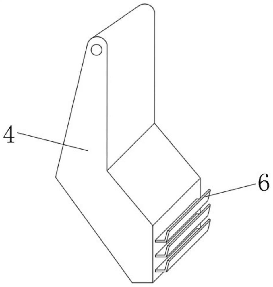
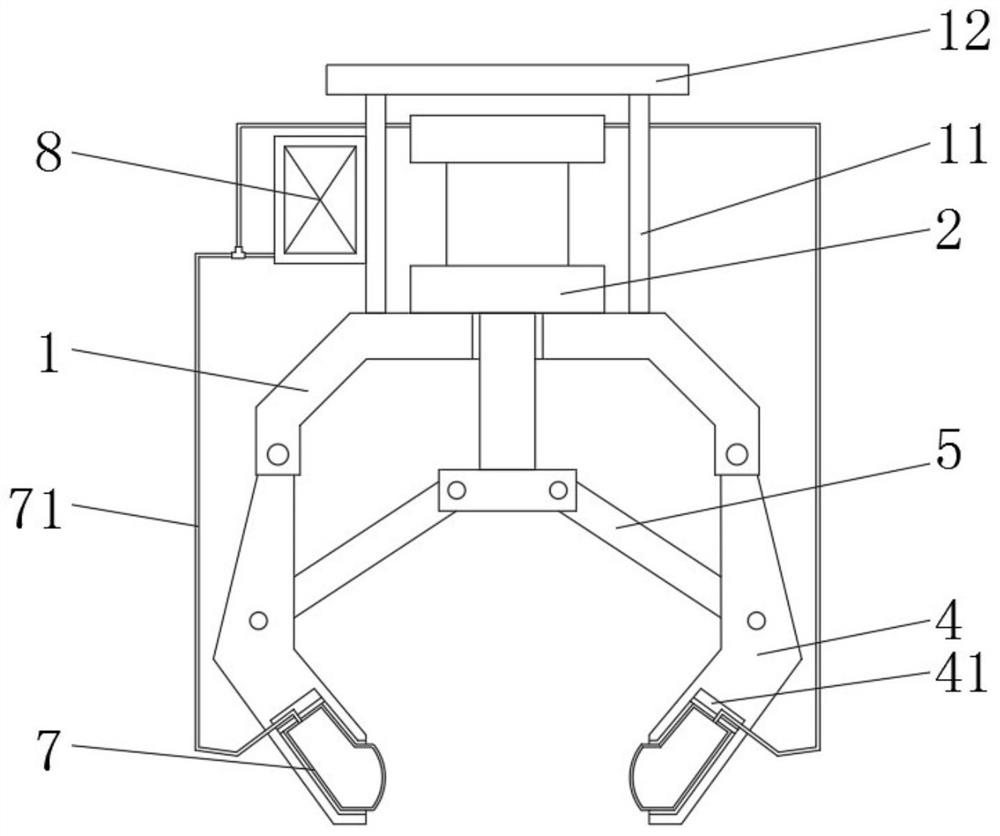
[0040] The lower end of the jaw 4 is provided with a holding groove 41, and a strength regulating air bag 7 is installed in the holding groove 41. The end can extend out of the receiving groove 41 to contact with the object, and the strength adjustment airbag 7 can exert a certain frictional force on the object clamped in the manipulator.

[0041] The outer wall of the vertical plate 11 is fixedly equipped with an air delivery assembly 8, the air delivery assembly 8 is connected with the strength adjustment airbag 7 through the air delivery pipe 71, the air delivery assembly 8 can deliver gas to the strength adjustment airbag 7, and the strength adjustment airbag 7 is filled with gas. After the gas is released, the protruding end can contact the side wall of the object, thereby generating a certain friction force on the object, so that the object can be firmly placed in the manipulator, effectively preventing t...

Embodiment 3

[0047] refer to Figure 5-8 , a further improvement made on the basis of Example 1:

[0048] The lower side of the connecting plate 3 is symmetrically installed with a strength adjustment assembly 9 front and back, and the strength adjustment assembly 9 can lift the object upwards, so that after the object is clamped by the manipulator, the hoisted object is supported by the strength adjustment assembly 9, and the object is supported by the strength adjustment assembly 9 by itself. The elastic force of the object lifts up the object, thereby reducing the gravity beared by the two jaws 4, so that the object is firmly placed between the jaws 4.

[0049] The force adjustment assembly 9 includes a circular sleeve 91 and a movable rod 92, one end of the movable rod 92 penetrates into the inside of the circular sleeve 91, and the two ends of the movable rod 92 are respectively fixedly connected with a limit plate 93, and the setting of the limit plate 93 can avoid The movable rod 9...


PUM


Abstract

The invention discloses an industrial robot capable of adjusting grabbing force and a using method of the industrial robot, and relates to the field of robotics. The industrial robot comprises a mounting base and an air cylinder fixedly mounted on the mounting base, clamping jaws are rotationally mounted at the two ends of the mounting base correspondingly, the output end of the air cylinder penetrates through the mounting base and is fixedly connected with a connecting plate, supporting rods are rotationally installed at the two ends of the connecting plate, the tail ends of the supporting rods are rotationally connected to clamping jaws, force adjusting pads are fixedly connected to the clamping positions of the lower ends of the clamping jaws, vertical plates are fixedly connected to the positions, located on the two sides of the air cylinder, of the upper side of the mounting base, and a mounting top plate is jointly and fixedly connected to the upper ends of the two vertical plates. The force adjusting pads are arranged on the clamping jaws of a manipulator, so that when the manipulator clamps an object, the friction force between the object and the manipulator is increased, the object is prevented from being damaged due to the fact that the object is separated from the manipulator, and the force adjusting pads can adjust deformation of themselves according to the weight of the object, and therefore, the manipulator has certain force adjusting capability.

Description

technical field [0001] The invention relates to the technical field of robots, in particular to an industrial robot with adjustable grasping strength. Background technique [0002] Today, as automation is getting higher and higher, human handling has gradually disappeared in factories, replaced by robotic arms and manipulators. Although robotic arms and manipulators do not need to rest, their work efficiency is very efficient, and they can replace manual work in harsh environments. However, traditional robotic arms and manipulators only achieve the best results on objects of a fixed shape and size, or grip different solid objects, but it is difficult for the robotic arm and manipulator to grasp the gripping force during the gripping process. During the clamping process, it is easy to cause damage to the device due to falling or excessive clamping force. Therefore, it is necessary to design an industrial robot that can adjust the grasping force. Contents of the invention ...

Claims


Application Information

Patent Timeline
Patent Type & Authority Applications(China)
IPC IPC(8): B25J15/00B25J15/02B25J15/08B25J9/14
CPCB25J15/0023B25J15/022B25J15/08B25J9/14
Inventor 毕登科朱亮
Owner 南京付联微网络科技有限公司
Why Eureka
Try Eureka