Novel crane hoisting equipment for industrial production
A hoisting equipment and hoisting technology, applied in the direction of hoisting equipment braking device, crane, hoisting device, etc., can solve the problems of mold equipment not being able to play external protection, potential safety hazards of upper and lower mold separation, poor stability, etc., to achieve easy adjustment. , easy to move and easy to operate
- Summary
- Abstract
- Description
- Claims
- Application Information
AI Technical Summary
Problems solved by technology
Method used
Image

Examples
Embodiment 1
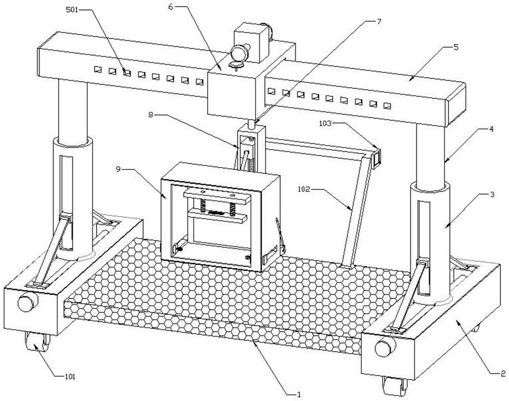
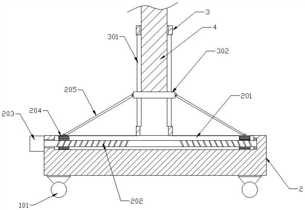
[0031] see Figure 1-7 As shown, this embodiment is a new type of crane hoisting equipment for industrial production, including a base frame 1, side supports 2 are connected to the left and right sides of the base frame 1, and a vertical sleeve is connected to the center of the top of the side support 2 3. A column 4 is plugged into the vertical casing 3, and the upper ends of the two columns 4 are jointly connected with a guide beam 5, and the outside of the guide beam 5 is provided with a moving seat 6, and the bottom of the moving seat 6 is rotatably connected with a steering shaft 7 The lower end of the steering shaft 7 is connected with a traction mechanism 8, the front end of the traction mechanism 8 is connected with a storage case 9, and the front end of the storage case 9 is opened.
[0032] The front and rear ends of the vertical casing 3 are provided with a vertical groove 301, and a lifting block 302 runs through the vertical groove 301. The top of the lifting bloc...
Embodiment 2
[0037] On the basis of Embodiment 1, a mounting frame 901 is connected to the lower part of the rear side wall of the storage case 9, and a winding shaft 902 is connected to the mounting frame 901 for rotation, and a winding motor 903 is connected to the left end of the winding shaft 902. The left and right sides of the outer wall of 902 are connected with a winding reel 904, the outer wall of the winding reel 904 is wound with a winding rope 905, and the left and right side walls of the storage shell 9 are provided with a slideway 906, which is slidingly connected with a workman in the slideway 906. Word block 907, the rear end of slideway 906 is provided with through hole, one end of unwinding rope 905 passing through hole is fixedly connected with I-shaped block 907, and the inner wall of I-shaped block 907 is connected with metal chain 908, and the movable end of metal chain 908 A lock 909 is connected.
[0038] The rear side wall of the inner cavity of the receiving shell...
Embodiment 3
[0043] On the basis of Embodiment 2, the traction mechanism 8 includes a fixed frame 801, the bottom of the inner cavity of the fixed frame 801 is connected with a lifting motor 802, the top power output end of the lifting motor 802 is connected with a vertical screw 803, and the outer wall of the vertical screw 803 A nut seat 2 804 is screwed, a free telescopic rod 805 is connected to the bottom of the front end of the fixed frame 801, and a support block 806 is connected to the front movable end of the free telescopic rod 805, and the support block 806 consolidates the bottom of the storage case 9, and the storage case 9 A drawbar 807 is hinged between the rear side wall of the top and the second nut seat 804.
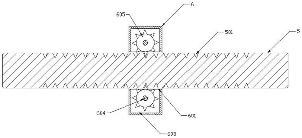
[0044] The front and rear ends of the guide beam 5 are symmetrically provided with straight tooth grooves 501, and the middle part of the moving seat 6 is provided with a through groove 601, and a plurality of universal ball heads 602 are installed on the upper and lo...
PUM
 Abstract
Description
Claims
Application Information
 - R&D
- Intellectual Property
- Life Sciences
- Materials
- Tech Scout
- Unparalleled Data Quality
- Higher Quality Content
- 60% Fewer Hallucinations
Browse by: Latest US Patents, China's latest patents, Technical Efficacy Thesaurus, Application Domain, Technology Topic, Popular Technical Reports.
© 2025 PatSnap. All rights reserved.Legal|Privacy policy|Modern Slavery Act Transparency Statement|Sitemap|About US| Contact US: help@patsnap.com