Basement bottom plate post-cast strip reserved drainage well rear sealing structure

A basement floor, closed structure technology, applied in underwater structures, infrastructure engineering, water conservancy engineering and other directions, can solve problems such as leakage of drainage wells, and achieve the improvement of work and life comfort, practicability, and operational procedures. clear effect

Pending Publication Date: 2022-01-28
CCFED THE FIGTH CONSTR & ENG +1
View PDF4 Cites 0 Cited by
  • Summary
  • Abstract
  • Description
  • Claims
  • Application Information

AI Technical Summary

Problems solved by technology

[0004] The invention provides a sealing structure reserved for the drainage well behind the basement bottom plate, so as to solve the problem of easy leakage when the drainage well is closed, and at the same time, it can be blocked in advance, and the water can continue to fall after sealing, meeting the anti-floating requirements At the same time, ensure that the follow-up construction is in an anhydrous working environment

Method used


Image

  • Basement bottom plate post-cast strip reserved drainage well rear sealing structure
  • Basement bottom plate post-cast strip reserved drainage well rear sealing structure
  • Basement bottom plate post-cast strip reserved drainage well rear sealing structure

Examples


Embodiment 1

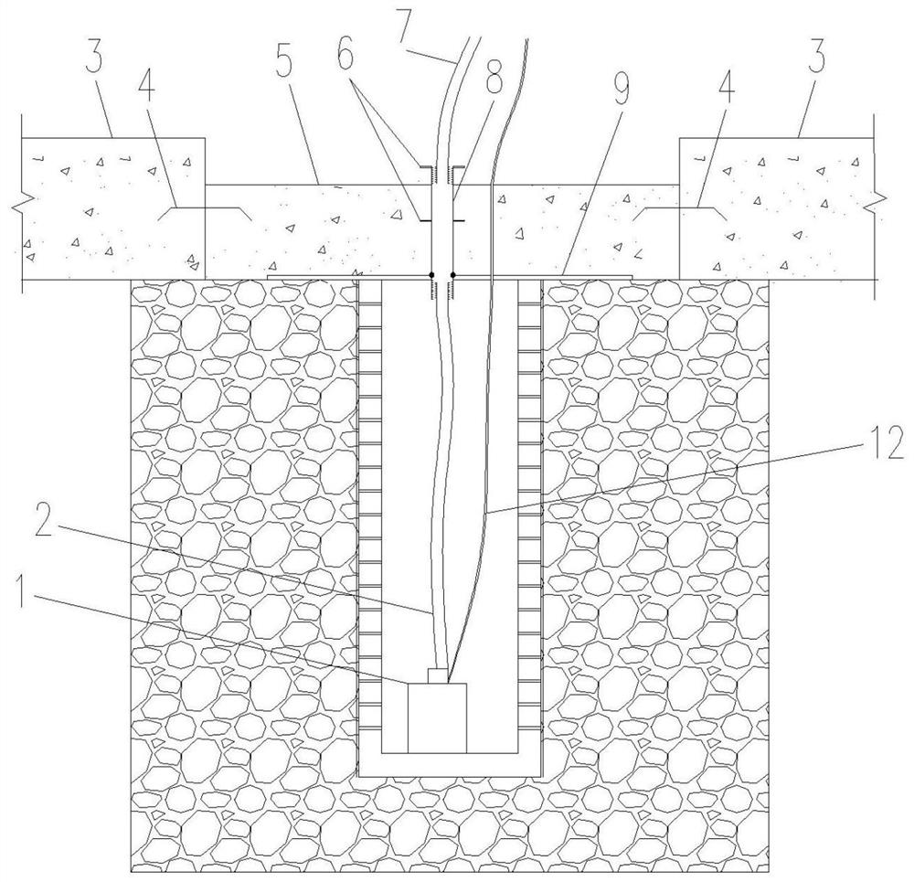
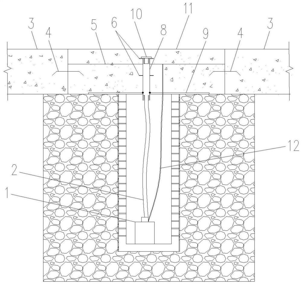
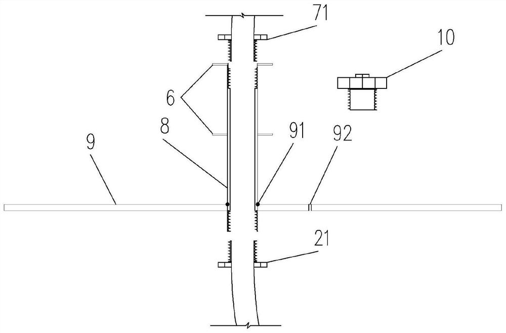
[0018] refer to Figure 1 to Figure 4 , the present embodiment provides a basement basement post-casting belt to reserve a closed structure behind the drain well, the upper end of the drain well is closed by a steel plate 9 covered, the steel plate 9 adopts a 20 mm thick steel plate, and the steel plate 9 is provided with a steel pipe hole 91 with a diameter of 50 mm The galvanized steel pipe 8 passes through the steel plate 9 through the steel pipe hole 91, and the periphery is fully welded. At the same time, a cable hole 92 with a diameter just enough to accommodate a 12-core cable is opened on the steel plate 9, so that the cable 12 connected to the water pump 1 is drawn out to the The external power supply supplies power to the water pump 1. The water pump 1 is permanently placed in the drainage well. The water inlet of the water pump 1 is wrapped with a filter screen. The water pump 1 is connected to one end of the water pipe 2 in the well. The water pipe joint 21 is thre...

Embodiment 2

[0036] Based on the method of closing the drain well after the basement floor post-pouring belt in the first embodiment, the improvement of this embodiment lies in:

[0037] When the groundwater level is high, the water volume is abundant, and the discharge wells have a lot of water, two or more water pumps 1 can be permanently embedded for pumping water, and one or more galvanized steel pipes 8 are correspondingly added to the steel plate 9 for pumping water. The principle of plugging is the same as that of Embodiment 1. The pumping rate is increased to ensure that the groundwater level is below the floor, which meets the construction requirements for anti-floating, and the quality of plugging can also be guaranteed.


PUM


Abstract

Disclosed is a basement bottom plate post-cast strip reserved drainage well rear sealing structure. A water pump is arranged in a drainage well, the upper end of the drainage well is sealed through a covered steel plate, a galvanized steel pipe penetrates through the steel plate, the water pump is connected with one end of an in-well water pipe, and the other end of the in-well water pipe is in butt joint with the lower end of the galvanized steel pipe. The upper end of the galvanized steel pipe is connected with the water pipe outside the well, or the other end of the water pipe inside the well is led out of the drainage well through the galvanized steel pipe and connected with the water pipe outside the well, and a cable hole is formed in the steel plate so that a cable connected with a water pump can be led out to an external power source. A first pouring surface is constructed above the steel plate; a water stop steel plate is constructed between the first pouring face and the bottom plate on the periphery, and a second pouring face is further constructed above the first pouring face. The problem that leakage is prone to occurring during post-sealing of the drainage well is solved, meanwhile, blocking can be conducted in advance, continuous precipitation can be conducted after blocking, and it is guaranteed that follow-up construction is in a waterless operation environment while the anti-floating requirement is met. The invention belongs to the field of engineering construction.

Description

technical field [0001] The invention relates to a closed structure behind a drain well reserved for a post-pouring belt of a basement bottom plate, belonging to the field of engineering construction. Background technique [0002] With the rapid development of my country's construction industry, there are more and more basements and other underground buildings in high-rise buildings, and the depth of underground buildings is getting deeper and deeper. Therefore, the problem of the impact of high water levels on the safety of underground structures is also faced People are paying more and more attention to it, and there are two most critical problems, one is the floating problem of the basement structure, and the other is the problem of water leakage in the basement. [0003] During the construction of the basement of the building, in order to ensure the smooth progress of the construction, it is necessary to carry out precipitation in advance. For areas with a high water level...

Claims


Application Information

Patent Timeline
Patent Type & Authority Applications(China)
IPC IPC(8): E02D19/10E02D29/16E02D31/12E02D31/02E02D15/02
CPCE02D19/10E02D29/16E02D31/12E02D31/02E02D15/02
Inventor 张佳盛陈法玉黄华峰章宇赵卓
Owner CCFED THE FIGTH CONSTR & ENG
Why Eureka
Try Eureka