Zero-carbon building cast-in-place concrete wall built-in heat preservation method and system

A concrete inner and concrete wall technology, applied in thermal insulation, construction, building components, etc., can solve the problems of not meeting the needs of zero-carbon buildings, old through-wall bolt casings are no longer applicable, and achieve simple structure, convenient construction, Good thermal insulation performance

Pending Publication Date: 2022-01-28
中康节能科技有限公司
View PDF2 Cites 0 Cited by
  • Summary
  • Abstract
  • Description
  • Claims
  • Application Information

AI Technical Summary

Problems solved by technology

However, the existing above-mentioned passive building wall-through bolt casings with airtight plugs can no longer meet the needs of zero-carbon buildings (ultra-low energy buildings, passive buildings, and near-zero energy buildings).
For example, compared with passive buildings in the past, zero-carbon buildings have significant changes in the weight and material of the insulation layer and the external additional layer, making the old wall-through bolt sleeves no longer applicable

Method used


Image

  • Zero-carbon building cast-in-place concrete wall built-in heat preservation method and system
  • Zero-carbon building cast-in-place concrete wall built-in heat preservation method and system
  • Zero-carbon building cast-in-place concrete wall built-in heat preservation method and system

Examples


Embodiment 1

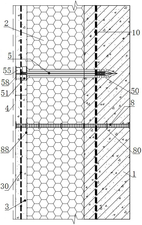
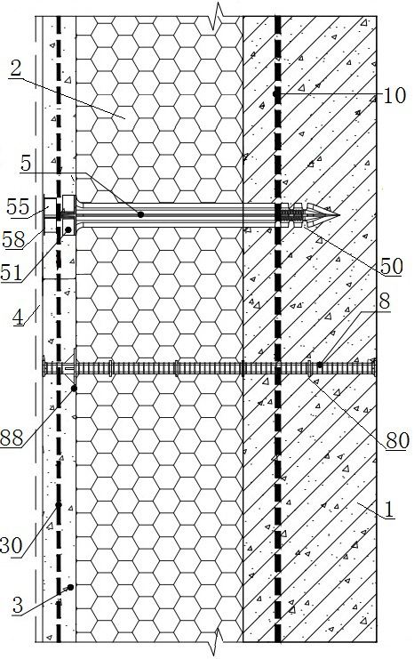
[0033] Example 1, such as Figure 1-2 And 4-16, a system for achieving a zero-carbon building in which a zero carbon building of the present invention is a hierarchical structure in which the wall from the wall is sequentially included in order, including the current pouring concrete layer 1, the insulation sheet layer 2 and concrete protective layer. The cast-in-place concrete layer 1 position is preset near the cast-in-condensed concrete of the thermal temperature plate layer 2, and the steel wire mezzanine 30 is preset from the solid concrete protective layer 3, and the cast-in-spot concrete is laminated. 30 is connected to the heat-free bridge connector for fixing the insulation plate layer 2, and the steel wire layer 10 and the insulation plate layer 2 and the steel wire mezzana of the self-compacting plate layer 3 in the current cast concrete layer 1. Retaining the wall bolt pneumatic tube 8 and the wall bolt and the two-end sealing plug, the pouring concrete layer 1 and the ...

Embodiment 2

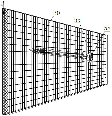
[0040] Embodiment 2, such as image 3 As shown, the difference between the insulation method and the system of the present invention and the above-described embodiment one of the above-described embodiments is provided between the limit fixation disk 88 and the outer circumference of the adjacent sleeve 88. Streduate a glibule to a uniform distributed bevel. It is also possible to provide a multi-circumferential homogeneous bevel reinforcing rib to the outer circumference of the outer circumference of the limit fixing plate and the outer circumference of the adjacent sleeve, and the restricted disk rear and adjacent sleeve The outer circumference is provided with multiple circumferential uniform distributed bevel reinforcement. Compared to the above-described embodiment, the support fixing strength of the restricted fixed disk on the insulation plate layer can be significantly enhanced.

[0041] In summary, the internal heat preservation method and system of the zero-carbon buildin...


PUM


Abstract

The invention relates to a zero-carbon building cast-in-place concrete wall built-in heat preservation method and system, and aims to meet the requirement of zero-carbon building wall built-in heat preservation. A wall body is of an inner cast-in-place concrete layer, a middle heat preservation plate layer and an outer concrete protection layer structure; through-wall bolt airtight pipes are arranged between soil inner binding steel bar layers in a penetrating mode, and the cast-in-place concrete inner binding steel bar layers close to the heat preservation plate layer are preset at the cast-in-place concrete layer pouring position and the self-compacting concrete protection layer pouring position; a steel wire mesh interlayer is preset at the position of the self-compacting concrete protection layer, and a heat-bridge-free connecting piece used for fixedly arranging the heat preservation plate layer is connected between the cast-in-place concrete inner binding steel bar layer and the steel wire mesh interlayer; and through-wall bolt airtight pipes, through-wall bolts and sealing plugs at the two ends are arranged between the steel wire mesh interlayer of the cast-in-place concrete layer and the heat preservation plate layer and the cast-in-place concrete inner binding reinforcing steel bar layer of the self-compacting concrete protection layer in a penetrating mode. The system has the advantages of being simple in structure, convenient to construct, capable of guaranteeing the structural strength of all layers of the wall and the whole wall and good in heat preservation and heat insulation performance.

Description

Technical field [0001] The present invention relates to a condensating method, in particular, to a zero-carbon building, currently casting a concrete method and system. Background technique [0002] The prior art has a cash-in-situ concrete built-in insulation structure including concrete layer, insulation plate and concrete protection layer, the concrete layer, the insulation plate and the concrete protective layer are arranged from right to left, and a right steel sheet is provided in the concrete layer. A fixing member and a wire are provided on both sides of the thermal plate, and a longitudinal steel wire is provided in the concrete layer and the concrete protective layer, and the fixing member is connected to a longitudinal steel wire. The connection wire lateral setting The left steel sheet is provided in the concrete protective layer. [0003] The right steel wire and the left steel wire are composed of 1-3 sets of steel wire mesh. The fixing member includes a screw that ...

Claims


Application Information

Patent Timeline
Patent Type & Authority Applications(China)
IPC IPC(8): E04B2/00E04B1/76E04B1/80E04B2/84
CPCE04B2/00E04B1/762E04B1/80E04B2/84E04B1/7629E04B1/7637Y02A30/244
Inventor 黄永申
Owner 中康节能科技有限公司
Why Eureka
Try Eureka