Permanent magnet motor with electrically-controlled hydraulic adjustable damping and heat dissipation housing

An electronically controlled hydraulic and permanent magnet motor technology, applied in electromechanical devices, electrical components, electric components, etc., can solve the problems of limited heat dissipation efficiency and insufficient shock absorption performance of permanent magnet motors, and improve shock absorption performance and work performance. , Improve the effect of fit

Active Publication Date: 2022-01-28
JIANGSU AEROSPACE POWER ELECTRIC
View PDF16 Cites 0 Cited by
  • Summary
  • Abstract
  • Description
  • Claims
  • Application Information

AI Technical Summary

Problems solved by technology

[0005] The technical problem to be solved by the present invention is: In order to solve the problems existing in the above-mentioned background technology, an improved permanent magnet motor with an electrically controlled hydraulically adjustable shock-absorbing and heat-dissipating cover is provided to solve the limited heat dissipation efficiency of the traditional permanent magnet motor. Moreover, rigid assembly methods are often used, and the shock absorption performance is insufficient.

Method used


Image

  • Permanent magnet motor with electrically-controlled hydraulic adjustable damping and heat dissipation housing
  • Permanent magnet motor with electrically-controlled hydraulic adjustable damping and heat dissipation housing
  • Permanent magnet motor with electrically-controlled hydraulic adjustable damping and heat dissipation housing

Examples


Embodiment Construction

[0026] The present invention is described in further detail now in conjunction with accompanying drawing. These drawings are all simplified schematic diagrams, which only illustrate the basic structure of the present invention in a schematic manner, so they only show the configurations related to the present invention.

[0027] In the description of the present invention, it should be noted that unless otherwise specified and limited, the terms "connected" and "connected" should be understood in a broad sense, for example, it can be a fixed connection, a detachable connection, or an integral Ground connection; it can be mechanical connection or electrical connection; it can be direct connection or indirect connection through an intermediary. Those of ordinary skill in the art can understand the specific meanings of the above terms in the present invention in specific situations.

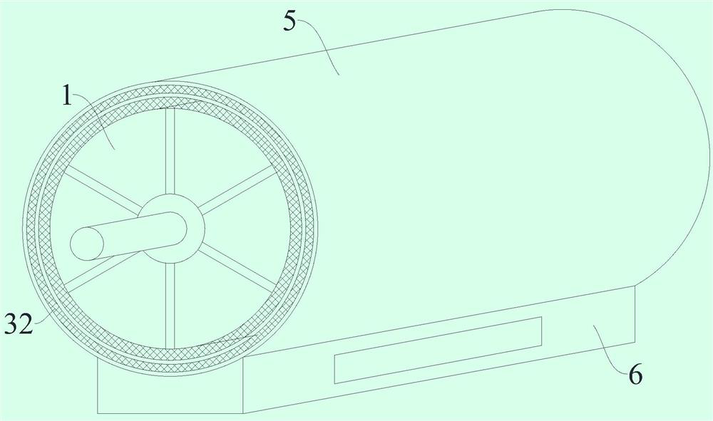
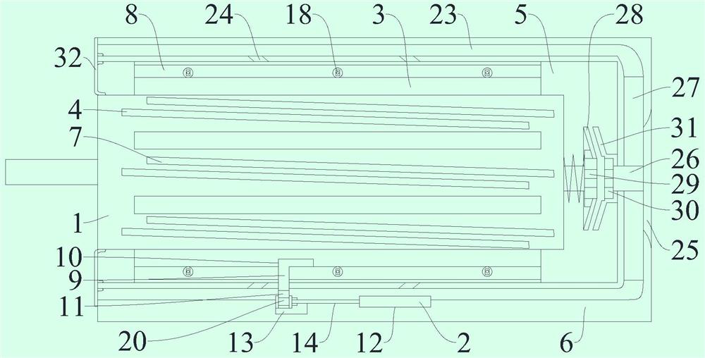
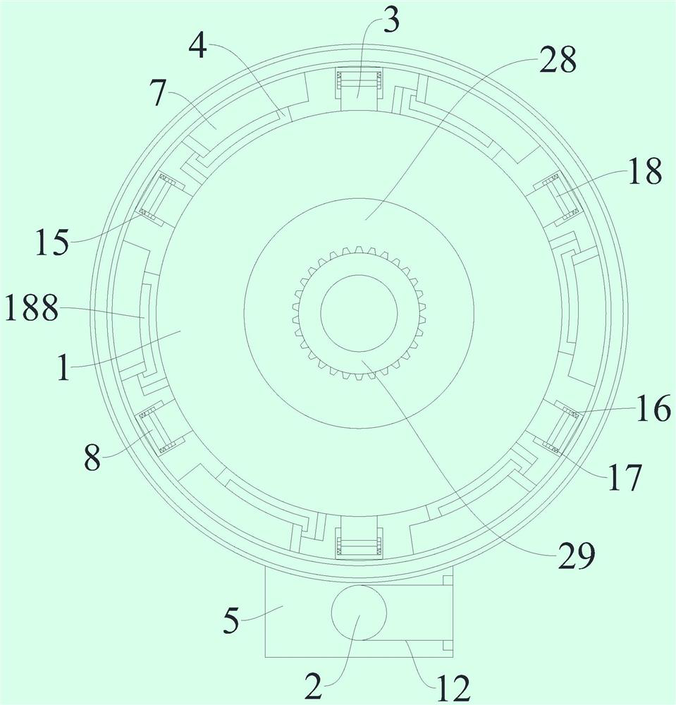
[0028] figure 1 , figure 2 and image 3 A permanent magnet motor with an electrically contro...


PUM


Abstract

The invention relates to the technical field of permanent magnet motors, and especially relates to a permanent magnet motor with an electrically-controlled hydraulic adjustable damping heat dissipation housing. The permanent magnet motor with the electrically-controlled hydraulic adjustable damping heat dissipation housing comprises a permanent magnet motor and an electrically-controlled hydraulic telescopic rod. According to the permanent magnet motor with the electrically-controlled hydraulic adjustable damping heat dissipation housing, transverse sliding blocks and obliquely-arranged strip-shaped heat dissipation sheets are arranged on the outer side face, and built-in transverse sliding rails and the obliquely-arranged strip-shaped heat conduction sheets are arranged on the periphery of the permanent magnet motor, so that rapid adjustment is achieved through the electrically-controlled hydraulic telescopic rods, the structure of the permanent magnet motor can be changed according to needs, the operation is simple, the permanent magnet motor can freely change the heat dissipation performance according to needs, and the working performance is greatly improved; and the strip-shaped heat dissipation sheets and the strip-shaped heat conduction sheets are arranged in an inclined mode, the distance between the strip-shaped heat dissipation sheets and the strip-shaped heat conduction sheets can be changed through transverse adjustment, the attaching performance of the strip-shaped heat dissipation sheets and the strip-shaped heat conduction sheets in the contact process can be improved through the graphene heat conduction films on the contact faces, and meanwhile the heat dissipation and conduction effect is enhanced.

Description

technical field [0001] The invention relates to the technical field of permanent magnet motors, in particular to a permanent magnet motor with an electrically controlled hydraulically adjustable shock-absorbing and heat-dissipating cover. Background technique [0002] Permanent magnet motors provide excitation with permanent magnets, which makes the motor structure relatively simple, reduces processing and assembly costs, and saves the collector rings and brushes that are prone to problems, improving the reliability of motor operation; and because no excitation is required current, without field losses, increasing the efficiency and power density of the motor. [0003] A permanent magnet motor consists of a stator, a rotor, and an end cover. The stator is basically the same as the ordinary induction motor, and adopts a lamination structure to reduce the iron loss when the motor is running. The rotor can be made solid or stacked with laminations. The armature winding can b...

Claims


Application Information

Patent Timeline
IPC IPC(8): H02K5/18H02K5/20H02K9/06H02K5/24
CPCH02K5/18H02K5/207H02K9/06H02K5/24Y02T10/64
Inventor 钱伟陈虎威赵勇陈帅朱尧孙烨锋
Owner JIANGSU AEROSPACE POWER ELECTRIC
Why Eureka
Try Eureka