Water pump with filter screen limiting system

A filter and water pump technology, which is applied to parts, pumps, and pump components of elastic fluid pumping devices, can solve problems such as inconvenient use, easy rotation or offset of the filter, and achieve the effect of accelerating circulation

Pending Publication Date: 2022-02-01
安徽川子泵阀密封有限公司
View PDF8 Cites 0 Cited by
  • Summary
  • Abstract
  • Description
  • Claims
  • Application Information

AI Technical Summary

Problems solved by technology

The existing water pump filter is not equipped with any restricting mechanism. When the filter does not need to be used for filtering, the filter is easy to rotate or shift under the impact of sundries and other impacts, which is inconvenient to use.

Method used


Image

  • Water pump with filter screen limiting system
  • Water pump with filter screen limiting system
  • Water pump with filter screen limiting system

Examples


Embodiment 1

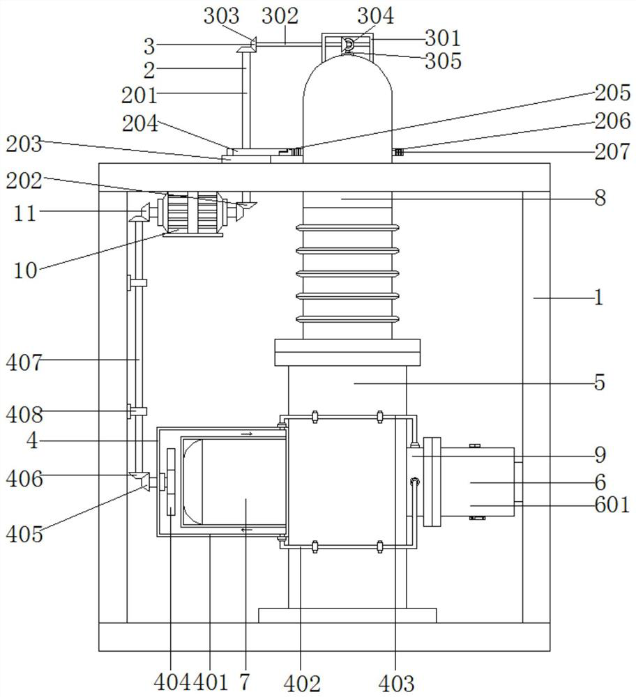
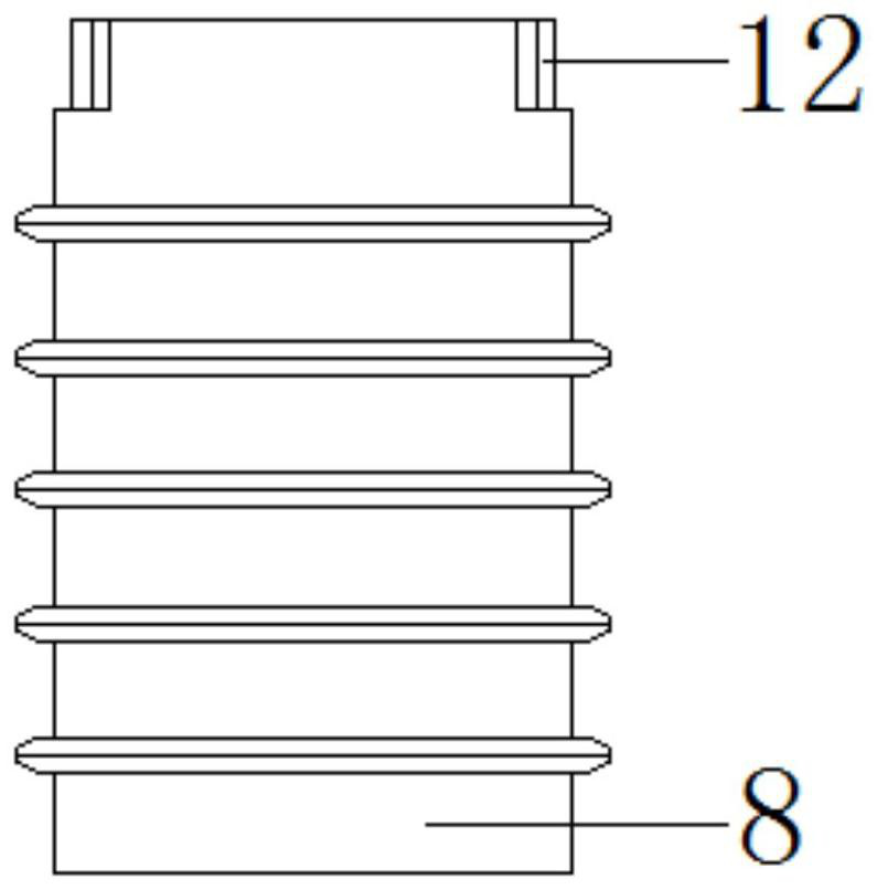
[0044] see Figure 1-7 , a water pump with a filter restricting system, comprising a frame 1 and a pump main body 5, the water pump main body 5 is fixedly connected above the bottom of the frame 1, a drive motor 7 is installed on one side of the water pump main body 5, and a connection is installed on the other side Pipeline 9, the top of water pump main body 5 is provided with drainpipe 8, and the bottom end of drainpipe 8 passes the top of frame 1, and is provided with sealed bearing 12 between the bottom end and the top of water pump main body 5; Sealed bearing 12 is to realize Rotary connection between the drain pipe 8 and the water pump main body 5 .

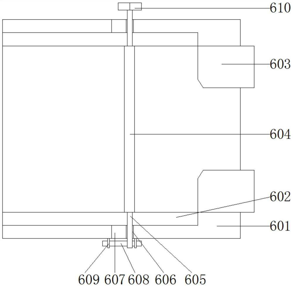
[0045] One side of the connecting pipe 9 is provided with a restricting mechanism 6, which includes a filter pipe 601, a moving pipe 602, a limit ring pipe 603, a filter screen 604, a rotating rod 605, a limit sleeve 606, a rectangular groove 607, and an adjustment rod 608 , fixed plate 609, adjustment handle 610 and isola...

Embodiment 2

[0048] see figure 1 , 8 , 9 and Figure 12 , one side of the drain pipe 8 is provided with a first adjustment mechanism 2, the first adjustment mechanism 2 includes a first transmission rod 201, a first bevel tooth 202, a first gear 203, a movable rod 204, a moving plate 205, a semicircular tooth Patterned plate 206, rectangular toothed plate 207, slide plate 208, clip bar 209 and second gear 210; one side of drain pipe 8 is fixedly connected with semicircular toothed plate 206, and one side tooth of semicircular toothed plate 206 A rectangular toothed plate 207 is connected together, a moving plate 205 is arranged on one side of the rectangular toothed plate 207, a sliding plate 208 is arranged on one side of the moving plate 205, the sliding plate 208 is fixedly connected to the top of the frame 1, and one end of the sliding plate 208 is provided with a movable Rod 204, one end of the movable rod 204 is provided with a first gear 203, the first gear 203 is rotatably connec...

Embodiment 3

[0052] see figure 1 , 8 , 10 and Figure 12 , the top of the drain pipe 8 is provided with a second adjustment mechanism 3, the second adjustment mechanism 3 includes a concave plate frame 301, a second transmission rod 302, a second bevel tooth 303, a third bevel tooth 304, a support rod 305, a curved rod 306, connecting rod 307 and blocking sheet 308; the top of the drain pipe 8 is provided with a concave plate frame 301, the inside of the concave plate frame 301 is provided with a second transmission rod 302, and the two ends of the second transmission rod 302 are provided with a second Bevel teeth 303, one side of a set of second bevel teeth 303 is engaged with third bevel teeth 304, one side of the third bevel teeth 304 is provided with a curved rod 306, and the two ends of the curved rod 306 are provided with support rods 305, And the middle end is provided with a connecting rod 307 , one end of the connecting rod 307 is provided with a blocking piece 308 , and one end...


PUM


Abstract

The invention discloses a novel agricultural water pump, which relates to the field of water pumps and comprises a frame and a water pump body. The water pump body is fixedly connected to the upper portion of the bottom of the frame, a driving motor is installed on one side of the water pump body, a connecting pipeline is installed on the other side of the water pump body, and a drainage pipe is arranged at the top end of the water pump body. The bottom end of the drainage pipe penetrates through the top of the frame, and a sealing bearing is arranged between the bottom end of the drainage pipe and the top end of the water pump body. According to the water pump with the filter screen limiting system, the limiting assembly is arranged, a limiting groove formed in a limiting ring pipe is used for limiting a filter screen, and the use problems that no limiting mechanism is arranged outside the filter screen of an existing water pump, and when the filter screen does not need to be used for filtering, the filter screen is easy to rotate or deviate under the impact force of sundries and the like, so that the water pump is inconvenient to use can be effectively solved.

Description

Technical field: [0001] The invention relates to the field of water pumps, in particular to a water pump with a filter net restriction system. Background technique: [0002] A pump is a machine that transports or pressurizes a liquid. It transmits the mechanical energy of the prime mover or other external energy to the liquid to increase the energy of the liquid. It is mainly used to transport liquids including water, oil, acid and alkali, emulsion, suspoemulsion and liquid metal. [0003] Liquids, gas mixtures and liquids containing suspended solids can also be transported. The technical parameters of pump performance include flow rate, suction lift, lift, shaft power, water power, efficiency, etc.; according to different working principles, it can be divided into volumetric pumps, vane pumps and other types. Positive displacement pumps use the change in the volume of their working chambers to transfer energy; vane pumps use the interaction between rotating blades and wat...

Claims


Application Information

Patent Timeline
Patent Type & Authority Applications(China)
IPC IPC(8): F04B17/03F04B53/08F04B53/20
CPCF04B17/03F04B53/08F04B53/20
Inventor 汪卫平唐子一占洋洋汪渌吴海洋黄文龙李建新
Owner 安徽川子泵阀密封有限公司
Why Eureka
Try Eureka