
Road roller gear shifting control device and road roller gear shifting control method

A control device and control method technology, applied in the direction of control device, transmission device control, mechanical equipment, etc., can solve the problems of reducing the reliability of the whole machine, reducing the service life of the friction plate, and many fault points, so as to improve the operating comfort, Reduce impact and noise and ensure compaction effect

Active Publication Date: 2022-02-01
SHANTUI CONSTR MASCH CO LTD
View PDF7 Cites 3 Cited by
  • Summary
  • Abstract
  • Description
  • Claims
  • Application Information

AI Technical Summary

Problems solved by technology

[0005] 1. Manual stepping is used to separate the main clutch and cut off the power transmission, which increases the labor intensity of the driver, and when the operator performs shifting and reversing, he needs to overcome the force of the return spring connected to the lower part of the pedal, which takes a long time Time operation will cause operator fatigue and affect customer comfort;
[0006] 2. Due to manual control, when the power transmission and cut-off are manually controlled, if the clutch is engaged too quickly, it will cause a strong mechanical impact on the friction plate, reduce the reliability of the clutch system, and affect the starting stability and operation quality of the roller; If the clutch engages too slowly, the wear of the friction plate will be accelerated and the service life of the friction plate will be reduced;
[0007] 3. The operation mode of the manual pedal clutch requires more actuators and more fault points, which reduces the reliability of the whole machine

Method used


Image

  • Road roller gear shifting control device and road roller gear shifting control method
  • Road roller gear shifting control device and road roller gear shifting control method
  • Road roller gear shifting control device and road roller gear shifting control method

Examples


Embodiment Construction

[0052]In order to make the technical problems solved by the present invention, the technical solutions adopted and the technical effects achieved clearer, the technical solutions of the embodiments of the present invention will be further described in detail below in conjunction with the accompanying drawings. Obviously, the described embodiments are only the technical solutions of the present invention. Some, but not all, embodiments. Based on the embodiments of the present invention, all other embodiments obtained by those skilled in the art without creative efforts fall within the protection scope of the present invention.

[0053] In the description of the present invention, unless otherwise clearly specified and limited, the terms "connected", "connected" and "fixed" should be understood in a broad sense, for example, it can be a fixed connection, a detachable connection, or an integrated ; It can be a mechanical connection or an electrical connection; it can be a direct ...


PUM


Abstract

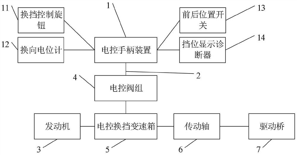
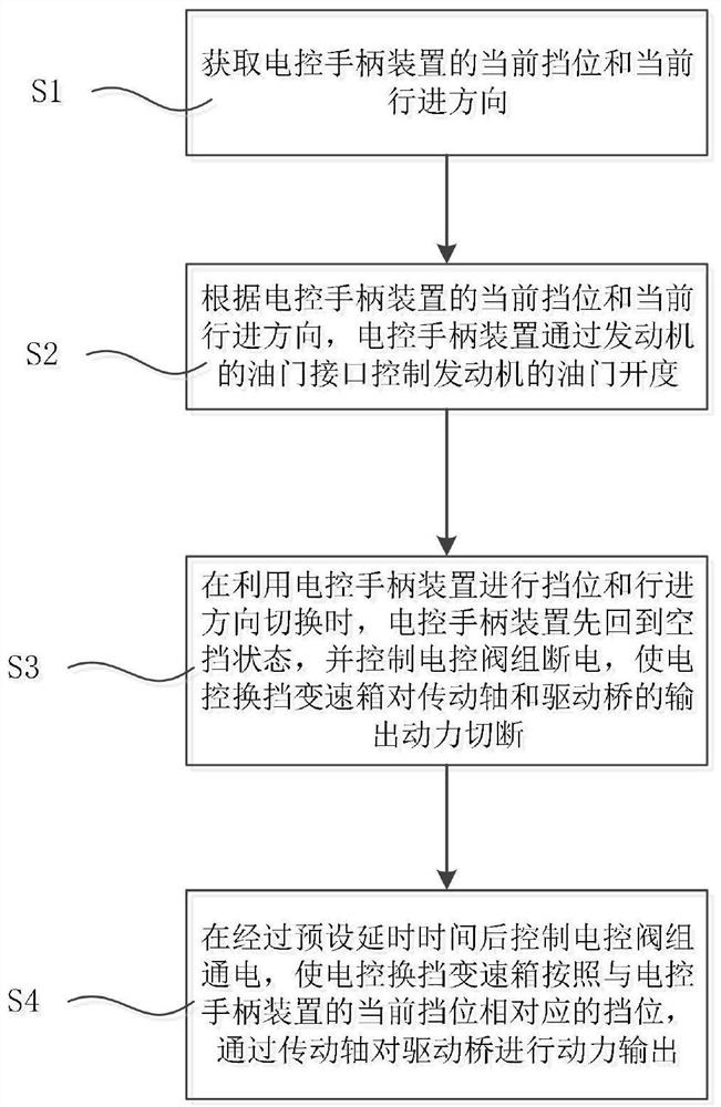
The invention belongs to the technical field of engineering machinery, and discloses a road roller gear shifting control device and a road roller gear shifting control method. The road roller gear shifting control device comprises an engine and an electric control gear shifting gearbox to which the output end of the engine is connected; a transmission shaft and a drive axle, the transmission shaft being arranged between the electric control gear shifting gearbox and the drive axle, and the electric control gear shifting gearbox being in transmission connection with the drive axle through the transmission shaft; an electric control handle device which is electrically connected to an accelerator interface of the engine; and an electric control valve group which is arranged on the electric control gear shifting gearbox and electrically connected to the electric control handle device, the electric control handle device being configured to control gear and advancing direction switching of the electric control gear shifting gearbox through the electric control valve group. According to the road roller gear shifting control device, the existing clutch pedal operation and a main clutch between the engine and the gearbox are removed, so that the structure of the whole machine is simplified, the cost of the whole machine is reduced, the labor intensity of operators is reduced, and the operation comfort is improved.

Description

technical field [0001] The invention relates to the technical field of engineering machinery, in particular to a gear shift control device for a road roller and a gear shift control method for a road roller. Background technique [0002] At present, the road roller is the key equipment for roadbed compaction in high-grade highway construction. Its driving mode is mechanical drive, that is, the engine transmits power to the clutch, and the clutch transmits the power to the transmission shaft. The transmission shaft transmits the power to the gearbox, and finally reaches the The driving axle drives the whole vehicle to drive. [0003] When the whole vehicle needs to start or change gears, step on the clutch pedal, the release fork of the clutch booster will move the release sleeve and the release bearing forward, push the inner end surface of the release rod, and move the pressure plate backward, and the friction plate and the end surface of the engine flywheel will move forwa...

Claims


Application Information

Patent Timeline
Patent Type & Authority Applications(China)
IPC IPC(8): F16H61/02F16H61/12B60K20/00
CPCF16H61/0213F16H61/12F16H61/04B60K20/00F16H2061/1216
Inventor 王涛卫吕浩黄志斌桑广波张梦宇黄国栋寻冠颖
Owner SHANTUI CONSTR MASCH CO LTD
Learn More