
Automatic spaceflight high-pressure inflation and deflation system and method

An aerospace automation, inflation and deflation technology, which is applied to the container filling method, the container discharge method, the equipment discharged from the pressure vessel, etc., can solve the problems of insufficient intelligence, low error tolerance rate of personnel operation, and many types of valves, etc.

Active Publication Date: 2022-02-01
TECH & ENG CENT FOR SPACE UTILIZATION CHINESE ACAD OF SCI
View PDF7 Cites 1 Cited by
  • Summary
  • Abstract
  • Description
  • Claims
  • Application Information

AI Technical Summary

Problems solved by technology

In the field of high-pressure inflation and deflation technology, the current high-pressure inflation and deflation system requires multiple people to work together, which is inefficient; data monitoring requires real-time interpretation by personnel, which is not smart enough; the inflation and deflation system has many types of valves, complex operation sequences, and a fault-tolerant rate of personnel operations Not high; the high-pressure inflation and deflation system involves the operation of high-pressure equipment, which is highly dangerous

Method used


Image

  • Automatic spaceflight high-pressure inflation and deflation system and method

Examples


Embodiment 1

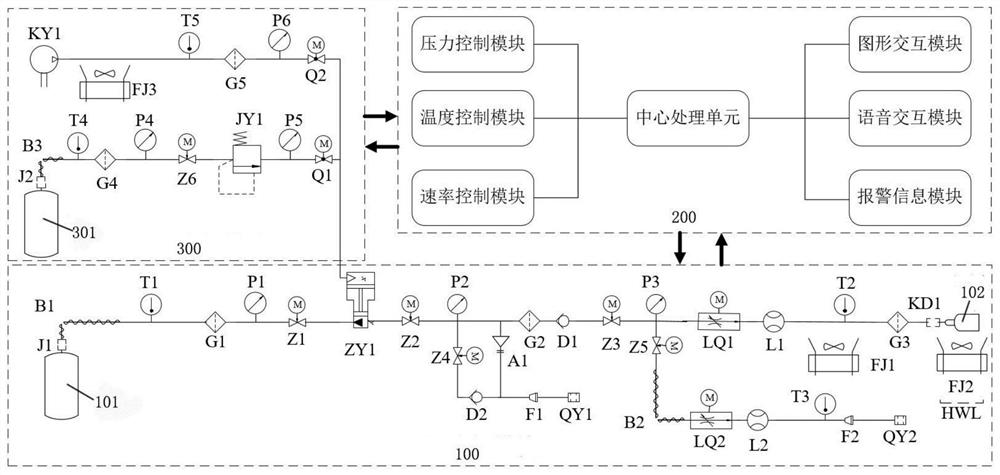
[0054] Such as figure 1 As shown, a kind of aerospace automatic high-pressure inflation and deflation system of the present embodiment includes a gas addition module 100, a driving gas module 300 and a control module 200; the gas addition module 100 includes a first standard gas cylinder 101, a target gas bottle 102 and an additional gas pipeline, a booster pump ZY1 is provided on the additional gas pipeline; the two ends of the additional gas pipeline are respectively connected to the first standard gas cylinder 101 and the target gas cylinder 102, and are used to convert the first The gas in the standard gas cylinder 101 is added to the target gas cylinder 102; the driving gas module is connected with the booster pump ZY1 through the driving gas pipeline;

[0055] A pressure detection component, a pressure regulation component, a temperature detection component and a temperature regulation mechanism are arranged on the added gas pipeline, and the pressure detection component...

Embodiment 2

[0068] Such as figure 1 As shown, on the basis of Embodiment 1, a first flow sensor L1 and a first flow regulating valve LQ1 are also provided on the added gas pipeline of this embodiment, and the first flow sensor L1 is used to collect the added gas The first gas flow signal in the gas pipeline is sent to the control module 200; the control module 200 controls the opening of the first flow regulating valve LQ1 according to the inflation pressure change rate and the first gas flow signal, While the rate of change of the inflation pressure of the additional gas pipeline is within a preset safe range, the gas flow rate of the additional gas pipeline is within a safe range of inflation flow. By setting the first flow sensor and the first flow regulating valve, the flow on the additional gas pipeline can be monitored, and the rate of change of the inflation pressure calculated according to the first gas pressure signal and the size of the gas flow signal collected by the flow sens...

Embodiment 3

[0070] Such as figure 1 As shown, on the basis of Embodiment 1 or Embodiment 2, the additional gas pipeline of this embodiment is also connected with a safety pressure relief pipeline, a first bleed pipeline, a first one-way valve D1 and a second bleed valve. The air pipeline, the safety relief pipeline and the first air release pipeline are located upstream of the first one-way valve D1 and downstream of the second pressure sensor P2; the third pressure regulating valve Z3 and the The second air release pipeline is located downstream of the first one-way valve D1, and the second air release pipeline is located upstream of the third pressure sensor P3; a safety valve A1 is connected to the safety pressure relief pipeline, The safety valve A1 is connected to the control module 200, and the control module 200 is used to control the safety valve A1 to open and release pressure when the first gas pressure signal exceeds a safety threshold; the first gas release pipeline It is use...


PUM


Abstract

The invention relates to an automatic spaceflight high-pressure inflation and deflation system and method. The system comprises a gas adding module, a gas driving module and a control module. The gas adding module comprises a first standard gas cylinder, a target gas cylinder and a gas adding pipeline, and a booster pump is arranged on the gas adding pipeline; the two ends of the gas adding pipeline are connected with the first standard gas cylinder and the target gas cylinder correspondingly, and the gas adding pipeline is used for adding gas in the first standard gas cylinder into the target gas cylinder. The gasdriving module is connected with the booster pump through a driving gas pipeline; a pressure detection assembly, a pressure adjusting assembly, a temperature detection assembly and a temperature adjusting mechanism are arranged on the gas adding pipeline, the pressure detection assembly is used for collecting a first gas pressure signal in the gas adding pipeline and sending the first gas pressure signal to the control module, and the temperature detection assembly is used for collecting a temperature signal of the gas adding pipeline and sending the temperature signal to the control module; the control module controls the pressure adjusting assembly to enable the inflation pressure change rate of the gas adding pipeline to be within a preset safety range. The control module regulates and controls the temperature of the gas adding pipeline to be within a preset temperature range.

Description

technical field [0001] The invention relates to the technical field of high-pressure inflation and deflation, in particular to an aerospace automation high-pressure inflation and deflation system and method. Background technique [0002] With the advancement of science and technology and the rapid development of industrial modernization, all kinds of equipment are developing in the direction of intelligence and integration. In the field of high-pressure inflation and deflation technology, the current high-pressure inflation and deflation system requires multiple people to work together, which is inefficient; data monitoring requires real-time interpretation by personnel, which is not smart enough; the inflation and deflation system has many types of valves, complex operation sequences, and a fault-tolerant rate of personnel operations Not high; the high-pressure inflation and deflation system involves the operation of high-pressure equipment, which is highly dangerous. [0...

Claims


Application Information

Patent Timeline
IPC IPC(8): F17C5/06F17C7/00F17C13/00F17C13/02F17C13/04
CPCF17C5/06F17C7/00F17C13/00F17C13/025F17C13/026F17C13/02F17C13/04F17C2227/0135F17C2227/0157F17C2250/043F17C2250/0439F17C2250/0626F17C2250/0631F17C2250/0694F17C2250/0443F17C2250/0636F17C2205/0352F17C2205/0388F17C2250/036F17C2250/072F17C2250/01F17C2227/0304F17C2227/0346F17C2270/0186Y02E60/32
Inventor 张聚乐王珂朱清淋冯振华吕从民卫晓娜管洪飞盛强张璐
Owner TECH & ENG CENT FOR SPACE UTILIZATION CHINESE ACAD OF SCI
Learn More