
Gangue throwing machine for mine backfilling and using method thereof

A technology for throwing gangue machines and mines, which is applied to filling materials, mining equipment, earth cube drilling and mining, etc. It can solve the problems of large space occupation, poor backfilling effect, and insufficient backfilling, and achieve good backfilling effect, small space occupation, and filling high rate effect

Pending Publication Date: 2022-02-08
山东金恒力能源科技有限公司
View PDF0 Cites 0 Cited by
  • Summary
  • Abstract
  • Description
  • Claims
  • Application Information

AI Technical Summary

Problems solved by technology

The gangue backfilling technology is to fill the gangue produced underground in the excavated coal roadway to replace the coal pillar, which can not only prevent the gangue from rising into the well, occupy the cultivated land, protect the environment, but also use the coal that cannot be extracted by conventional methods. Resources are mined to improve the resource output rate. Waste rock backfilling usually uses a dumping machine. The dumping machine can throw the gangue into the roadway through an upwardly inclined belt conveyor, and can move by itself, so as to realize the continuous movement while throwing. operation, the existing gangue dumping machine takes up a lot of space and is not suitable for narrow mines, and the backfilling effect on the top of the roadway is poor, which may easily cause the top backfilling to not be in place

Method used


Image

  • Gangue throwing machine for mine backfilling and using method thereof
  • Gangue throwing machine for mine backfilling and using method thereof
  • Gangue throwing machine for mine backfilling and using method thereof

Examples


Embodiment Construction

[0036] In order to clearly describe the technical characteristics of the present plan, the plan will be described below by way of example.

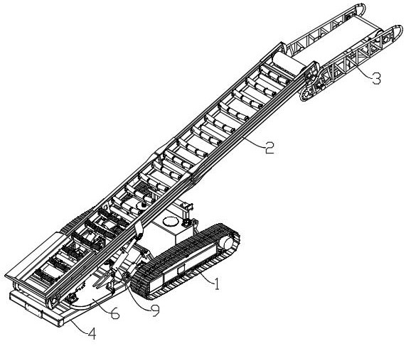
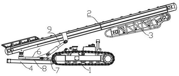
[0037] like Figure 1 ~ 7 As shown, a mine back filling of the present invention, including the travel mechanism 1, the main belt conveyor 2, and the end belt conveyor 3, the travel mechanism 1 is the crawler traveling mechanism, which can accommodate complex in the mineral cave. The road condition, which is convenient to advance, backward, and steering, the upper end described in this application is not necessarily the uppermost position, and also includes positions close to the upper end, the lower ends described in this application are not necessarily the position, also Contains positions close to the lower end.

[0038] The main belt conveyor 2 is tilted and hinges with the traveling mechanism 1, the main belt conveyor 2 throws the material upward, the front side of the throwing direction is the front side of the throwing machine, and the ...


PUM


Abstract

The invention relates to a gangue throwing machine for mine backfill and a using method thereof. The gangue throwing machine comprises a walking mechanism, a main belt conveyor and an end belt conveyor, the main belt conveyor is obliquely arranged and hinged to the walking mechanism, the lower end of the main belt conveyor is located behind the walking mechanism, and the upper end of the main belt conveyor is located in front of the walking mechanism; one end of the end belt conveyor is hinged with the upper end of the main belt conveyor, the pitching driving device is used for driving the main belt conveyor to pitch up and down, and the end driving device is used for driving the end belt conveyor to swing up and down relative to the main belt conveyor. High-speed throwing is achieved through the end belt conveyor, the throwing speed can be adjusted, different throwing angles can be provided by adjusting the angle of the end belt conveyor, backfilling of the top of a roadway is facilitated, and the device is small in occupied space, good in backfilling effect and capable of adapting to backfilling operation of various mine holes.

Description

Technical field [0001] The present invention relates to the field of tap, specifically, refers to a mine back filling tuning machine and its use. Background technique [0002] In the prevention and control measures of the existing mining sink, the toron filling technology can control the ground subsidence, reducing the raised rate of the gangue and is widely accepted. The mete backfilling technology is to fill the gangue produced under the exhaustion of the coal. The resource is produced, and the resource output rate is improved. The meteorite backfill is usually used by a tap. The throwing machine can be thrown into the roadway by tilting the tilted tape conveyor, and can move itself, thus achieving continuous edge movement. Homework, existing throwing machines are large, not suitable for small minens, and is poor to be in place for the top back of the backfill. Inventive content [0003] The present invention is directed to the shortcomings of the prior art, providing a mine b...

Claims


Application Information

Patent Timeline
IPC IPC(8): E21F15/06E21F13/00
CPCE21F15/06E21F13/00
Inventor 罗华君方伟
Owner 山东金恒力能源科技有限公司
Learn More