Sowing equipment used for heavy metal soil remediation and capable of plant sowing and burying
A soil remediation and heavy metal technology, applied in the restoration of contaminated soil, sowing, planting methods, etc., can solve the problems of inconvenient repair and low work efficiency, and achieve the effect of promoting repair and growth
- Summary
- Abstract
- Description
- Claims
- Application Information
AI Technical Summary
Problems solved by technology
Method used
Image
Examples
Embodiment 1
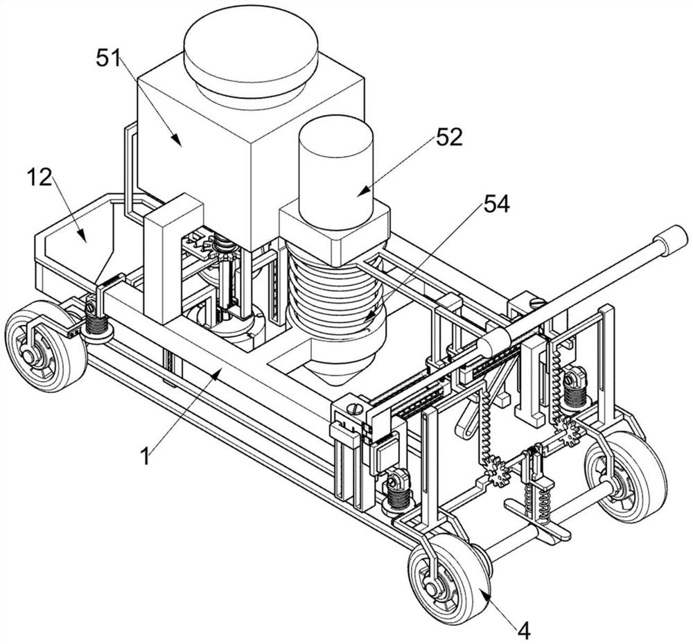
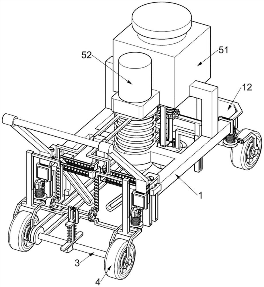
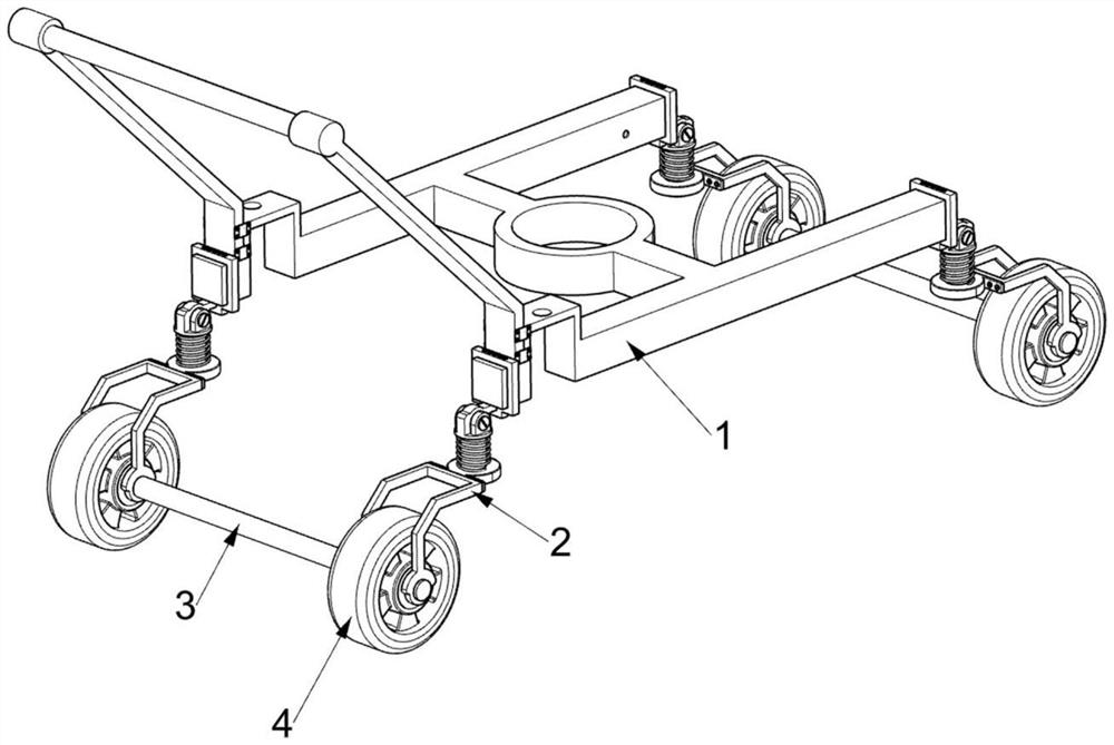
[0041] A kind of sowing equipment for heavy metal soil remediation that can sow and bury plants, such as Figure 1-6 Shown, comprise pushing frame 1, shock absorbing frame 2, rotating shaft 3, wheel 4, sowing assembly 5, belt pulley 6 and power band 7, rectangular distribution is arranged on pushing frame 1 and is connected with four for shock-absorbing by bolt. The shock mount 2 is connected with a rotating shaft 3 in common rotation between the same pair of shock absorbing mounts 2, and a wheel 4 is connected with a symmetrical rotation on the rotating shaft 3. The wheel 4 is used to assist people to push the equipment to move. The sowing assembly 5 for ground sowing is fixedly connected with a pulley 6 on the rotating shaft 3, and a power belt 7 is wound between the two pulleys 6.
[0042] The sowing assembly 5 includes a sowing material box 51, a sowing bar 52, a pressure bar 53 and a first return spring 54. The pushing frame 1 is fixedly connected with a sowing material b...
Embodiment 2
[0045] On the basis of Example 1, such as Figure 7-8 As shown, it also includes a pressing assembly 8, which is used to replace the pressing assembly 8 of manually pushing the pressing rod 53 and is arranged on one of the pair of shock absorbers 2. The pressing assembly 8 includes a cam 81, a special-shaped slotted frame 82 , sliding rack frame 83, second back-moving spring 84, T-shaped slotted frame 85, L-shaped rack frame 86, rotating shaft 87, bull gear 88 and pinion 89, wherein one rotating shaft 3 is fixedly connected with cam 81 , wherein a pair of shock mounts 2 are jointly fixedly connected with a special-shaped slotted frame 82, and the special-shaped slotted frame 82 is slidably connected with a sliding rack frame 83, the sliding rack frame 83 is located above the cam 81, and the sliding rack frame 83 is in contact with the cam 81, and a pair of second return springs 84 for driving the sliding rack frame 83 to reset are connected between the sliding rack frame 83 an...
Embodiment 3
[0048] On the basis of Example 2, such as Figure 9-11 Shown, also includes digging assembly 9, is used for digging the digging assembly 9 of groove on the soil and is located on push frame 1, and digging assembly 9 includes special-shaped slide rail frame 91, special-shaped grooved disc 92, The 3rd back-moving spring 93, sheave bar 94, band bar press ring 95, the 4th back-moving spring 96 and expansion frame 97, on the pushing frame 1, be connected with special-shaped slide rail frame 91 by bolt, on the special-shaped slide rail frame 91 sliding type A special-shaped slotted disc 92 is connected, and the lower part of the special-shaped slotted disc 92 has a disc structure. A pair of third return springs 93 for driving the special-shaped slotted disc 92 to reset are connected between the special-shaped slotted disc 92 and the special-shaped slide rail frame 91 , the special-shaped slide rail frame 91 is rotatably connected with a sheave bar 94, the bottom of the sheave bar 94...
PUM
 Abstract
Description
Claims
Application Information
 - R&D
- Intellectual Property
- Life Sciences
- Materials
- Tech Scout
- Unparalleled Data Quality
- Higher Quality Content
- 60% Fewer Hallucinations
Browse by: Latest US Patents, China's latest patents, Technical Efficacy Thesaurus, Application Domain, Technology Topic, Popular Technical Reports.
© 2025 PatSnap. All rights reserved.Legal|Privacy policy|Modern Slavery Act Transparency Statement|Sitemap|About US| Contact US: help@patsnap.com


