Wire winding support of tire bead steel wire winding machine

A bead steel wire and winding machine technology, applied in the field of bead steel wire processing, can solve the problems of easy bending of the steel wire, small bending angle of the steel wire, and reduction of the winding quality of the steel wire, so as to increase flexibility, improve the conveying effect, increase the The effect of the delivery effect

Active Publication Date: 2022-02-11
SHANDONG SNTON STEEL CORD
View PDF12 Cites 0 Cited by
  • Summary
  • Abstract
  • Description
  • Claims
  • Application Information

AI Technical Summary

Problems solved by technology

[0005] (1) When the existing winding frame is in use, the wire winding wheel is used to wire and wind the wound bead steel wire, while the general wire winding wheel will run along the wire coil during the use of the general wire winding frame The reciprocating movement is carried out in the direction of the receiving wheel, and when the steel wire on the wire-discharging wheel enters the position of the wire-discharging wheel, the edge of the steel wire is prone to wrinkles, so that the edge of the steel wire is prone to bending, and the steel wire on the wire-discharging wheel It is easy to have a small bending angle, which will lead to stress deformation of the steel wire and reduce the winding quality of the steel wire
[0006] (2) During the use of the existing equipment and the winding machine, the wire mechanism of the winding machine often uses multiple guide wheels to clamp the upper and lower wires and transport the bead wires. When the steel wire is conveyed, the steel wire is easy to bend at different angles, which reduces the conveying effect of the steel wire

Method used


Image

  • Wire winding support of tire bead steel wire winding machine
  • Wire winding support of tire bead steel wire winding machine
  • Wire winding support of tire bead steel wire winding machine

Examples


Embodiment 1

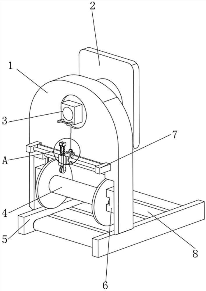
[0043] like Figure 1-Figure 13 As shown, the present invention provides a wire winding support for a bead wire winding machine, comprising a support plate 1, a conveyor belt fixing frame 5 is arranged below the support plate 1, a groove is opened under the support plate 1, and the support plate 1 The inner side of the lower groove is provided with a winding wheel installation mechanism 6, the back of the support plate 1 is provided with a rear plate 2, the side of the support plate 1 away from the rear plate 2 is provided with a wiring guide assembly 7, and the outside of the support plate 1 is provided with through holes , and a torsion mechanism 3 is arranged in the external through hole of the support plate 1;

[0044] The conveyor belt fixing frame 5 under the support plate 1 plays the role of fixing the conveyor belt 8, and at the same time, the winding wheel installation mechanism 6 in the groove under the supporting plate 1 can lift the workpiece winding wheel 4, so th...

Embodiment 2

[0058] Based on a wire winding support for a bead wire winding machine provided in the first embodiment of the present application, another wire winding support for a bead wire winding machine is proposed in the second embodiment of the present application. The second embodiment is only a preferred mode of the first embodiment, and the implementation of the second embodiment will not affect the independent implementation of the first embodiment.

[0059] The second embodiment of the present invention will be further described below with reference to the accompanying drawings and embodiments.

[0060] Based on the first embodiment, the difference between the second embodiment and the first embodiment is that the second embodiment also has a take-up wheel installation mechanism 6 .

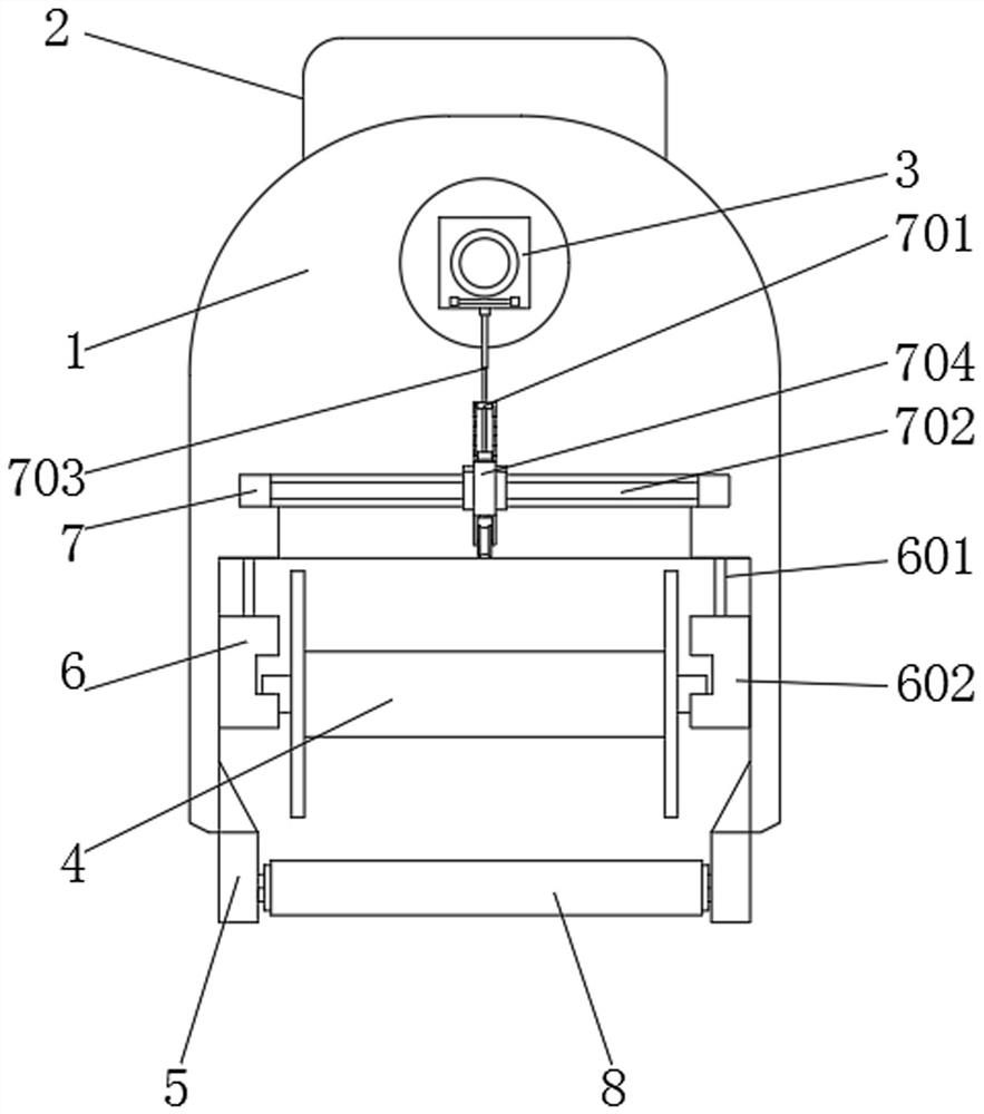
[0061] The rewinding wheel installation mechanism 6 includes a telescopic electric cylinder 601. There are two sets of telescopic electric cylinders 601. The two sets of telescopic electric cylinder...

Embodiment 3

[0066]Based on a wire winding support for a bead wire winding machine provided in the first embodiment of the present application, the third embodiment of the present application proposes another wire winding support for a bead wire winding machine. The third embodiment is only a preferred mode of the first embodiment, and the implementation of the third embodiment will not affect the independent implementation of the first embodiment.

[0067] The third embodiment of the present invention will be further described below with reference to the accompanying drawings and embodiments.

[0068] Based on the first embodiment, the difference between the third embodiment and the first embodiment is that the third embodiment also has a wiring guide assembly 7 .

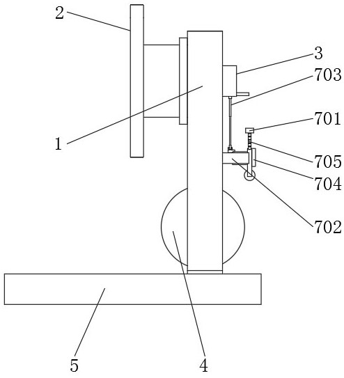
[0069] Specifically, the wiring guide assembly 7 includes a screw slide table 702, and the screw slide table 702 is slidably provided with a sliding base 707 outside, the outer wall of the sliding base 707 is provided with a g...


PUM


Abstract

The invention relates to the technical field of tire bead steel wire processing, in particular to a wire winding support of a tire bead steel wire winding machine. The wire winding support comprises a supporting plate, a conveying belt fixing frame is arranged below the supporting plate, and a groove is formed below the supporting plate; a winding wheel mounting mechanism is arranged at the inner side of the groove below the supporting plate, a rear plate is arranged on the back face of the supporting plate, and a wiring guide assembly is arranged on the face, away from the rear plate, of the supporting plate; a through hole is formed in the outer portion of the supporting plate, and a twisting mechanism is arranged in the through hole in the outer portion of the supporting plate. The twisting mechanism comprises a rotating bearing, a guiding assembly and a fastening wheel driving assembly, and the rotating bearing is arranged in a through hole in the outer portion of the supporting plate. According to the present invention, the twisting mechanism is arranged, a steel wire is guided in a preset mode through the twisting mechanism, the situation that the steel wire is twisted by a smaller angle can be prevented, the deformation of the steel wire due to a too small torsion angle is avoided, and the conveying effect of the steel wire is improved.

Description

technical field [0001] The invention relates to the field of bead wire processing, in particular to a wire winding support for a bead wire winding machine. Background technique [0002] Bead wires are made of high carbon steel with bronze or brass plated wires. It has high strength, high toughness, excellent fatigue resistance and good linearity, and has high adhesion to rubber. The bead steel wire and the isolation rubber are woven into a bead ring, which tightly fixes the tire on the rim and bears the forces of tension, compression, torsion and centrifugal force during the driving of the vehicle. The bead wire plays an important role in enhancing the performance of the tire and is essential to ensure the driving safety of the vehicle. [0003] The Chinese invention patent (CN202669009U) discloses that the present invention discloses a six-station tire bead winding machine, which includes a body, a sliding shaft and a winding disc. The body is slidably connected with a li...

Claims


Application Information

Patent Timeline
Patent Type & Authority Applications(China)
IPC IPC(8): B21F37/00B29D30/48
CPCB21F37/00B29D30/48
Inventor 窦勇王志伟王继峰李金磊王培峰陈军
Owner SHANDONG SNTON STEEL CORD
Why Eureka
Try Eureka