Supercharge Your Innovation With Domain-Expert AI Agents!

Clamp and method for surfacing layers on two side surfaces of boss of metal plate welding flame tube ferrule

A technology of flame cylinder and surfacing layer, which is applied in the field of gas turbine engine repair, can solve problems such as failure to meet the repair cycle requirements of gas generators, complex structure of special tooling, and long design and manufacturing cycle, so as to achieve high flexibility in structural design and improve application The effect of ingenious and structural design

Active Publication Date: 2022-02-11
AECC AVIATION POWER CO LTD
View PDF14 Cites 0 Cited by
  • Summary
  • Abstract
  • Description
  • Claims
  • Application Information

AI Technical Summary

Problems solved by technology

[0004] In order to overcome the above-mentioned shortcomings of the prior art, the purpose of the present invention is to provide a fixture and method for the surfacing layer on both sides of the boss of the flame tube ferrule for sheet welding, so as to solve the problem of repairing the flame tube assembly without special tooling in the prior art , the special tooling for conventional repair methods has complex structures, large outline dimensions, high manufacturing costs, long design and manufacturing cycles, and cannot meet the repair cycle requirements of gas generators.

Method used


Image

  • Clamp and method for surfacing layers on two side surfaces of boss of metal plate welding flame tube ferrule
  • Clamp and method for surfacing layers on two side surfaces of boss of metal plate welding flame tube ferrule
  • Clamp and method for surfacing layers on two side surfaces of boss of metal plate welding flame tube ferrule

Examples


Embodiment Construction

[0046] In order to enable those skilled in the art to better understand the solutions of the present invention, the following will clearly and completely describe the technical solutions in the embodiments of the present invention in conjunction with the drawings in the embodiments of the present invention. Obviously, the described embodiments are only It is an embodiment of a part of the present invention, but not all embodiments. Based on the embodiments of the present invention, all other embodiments obtained by persons of ordinary skill in the art without making creative efforts shall fall within the protection scope of the present invention.

[0047] It should be noted that the terms "first" and "second" in the description and claims of the present invention and the above drawings are used to distinguish similar objects, but not necessarily used to describe a specific sequence or sequence. It is to be understood that the data so used are interchangeable under appropriate ...


PUM


Abstract

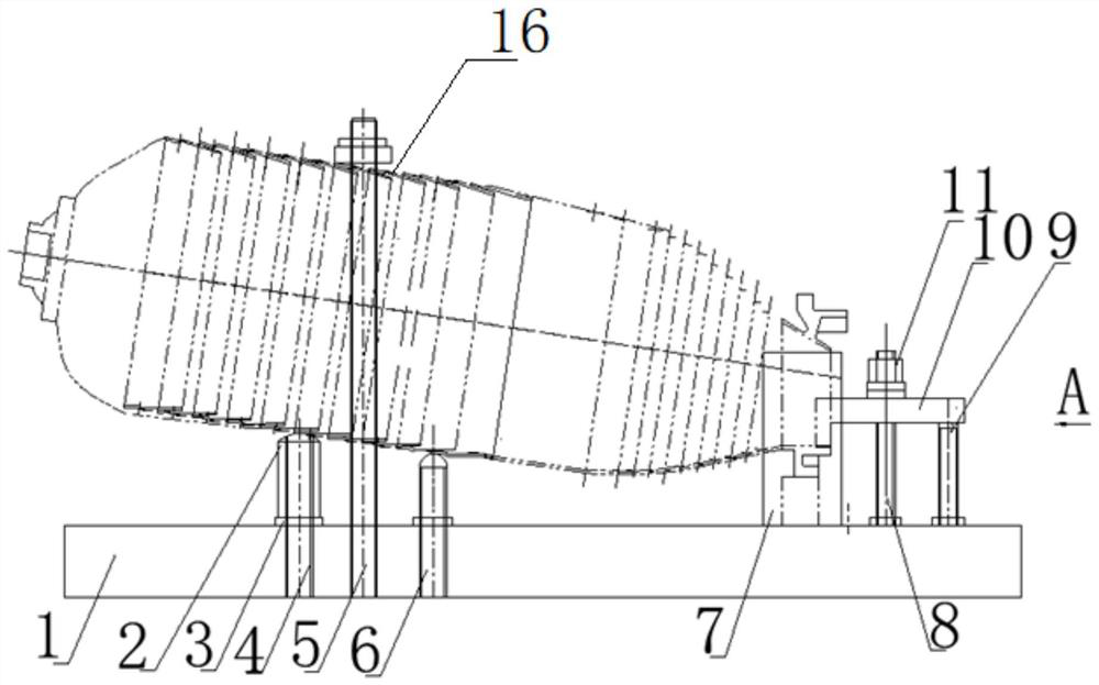
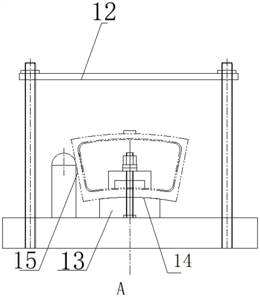
The invention discloses a clamp and method for surfacing layers on the two side surfaces of a boss of a metal plate welding flame tube ferrule, and belongs to the field of gas turbine engine repairing. The clamp comprises a foundation bottom plate, a positioning unit, a pressing unit and an auxiliary adjusting and supporting unit, wherein the positioning unit, the pressing unit and the auxiliary adjusting and supporting unit are matched with one another, the flame tube is redesigned, positioned and pressed according to the assembly state of the flame tube, and the problem that no special tool is available is solved. According to the method, when the flame tube of the fuel gas generator is repaired, a clamp is adopted for positioning, and the characteristics of a numerical control machine tool are utilized, when milling machining is conducted on each flame tube ferrule boss before surfacing welding, tool setting coordinate values of one side of each ferrule boss are recorded, and after milling machining, surfacing welding and local stress relieving are conducted on the flame tube ferrule bosses, and according to the tool setting coordinate values of the side surfaces of the flame tube ferrule bosses, the side surfaces of the flame tube ferrule bosses are machined to the recorded coordinate values of the corresponding numerical control machine tool. The method has the advantages of being economical, reliable and practical in scheme, good in operability and stable in finished product quality.

Description

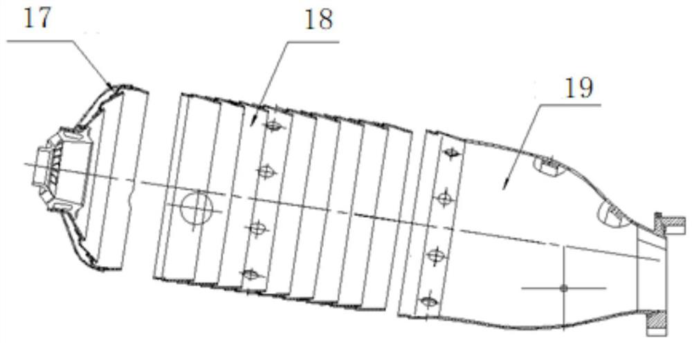
technical field [0001] The invention belongs to the field of gas turbine engine repair, and in particular relates to a fixture and a method for surfacing layers on both sides of a flange of a flame tube ferrule for sheet welding. Background technique [0002] The tubular sheet-welded flame tube structure of a certain gas turbine engine is a segmented superimposed combined weldment, which consists of three parts: the flame tube head assembly, the flame tube middle cone assembly and the gas conduit assembly. The ferrule of the end part of the flame tube gas pipe assembly is a precision casting fan-shaped part. The material of the ferrule is 10Cr30Ni50WMoAlTiNb superalloy material. There is a boss on the ferrule. When the part is in state, it is milled to ensure the final design. Dimensions: width 20 -0.11 -0.24 mm, the effective depth is 7mm, and the symmetry between the center of the boss and the center of the ferrule is 0.2mm. When the flame tube is assembled and welded, t...

Claims


Application Information

Patent Timeline
IPC IPC(8): B23C9/00B23Q3/06B23P15/00
CPCB23C9/00B23Q3/06B23P15/00Y02T50/60
Inventor 司松社霍潮峰胡斌高亚娟王涛
Owner AECC AVIATION POWER CO LTD
Features
  • R&D
  • Intellectual Property
  • Life Sciences
  • Materials
  • Tech Scout
  • Unparalleled Data Quality
  • Higher Quality Content
  • 60% Fewer Hallucinations
Learn More