
Push-pull power amplification circuit and radio frequency front-end module

A power amplifier circuit and power amplifier tube technology, applied in power amplifiers, push-pull amplifiers, amplifiers, etc., can solve the problem of large output loss of push-pull power amplifier circuits, reduce output loss, reduce design costs, and design flexibility Effect

Pending Publication Date: 2022-02-11
RUIPAN MICROELECTRONICS TECH (SHANGHAI) CO LTD
View PDF0 Cites 2 Cited by
  • Summary
  • Abstract
  • Description
  • Claims
  • Application Information

AI Technical Summary

Problems solved by technology

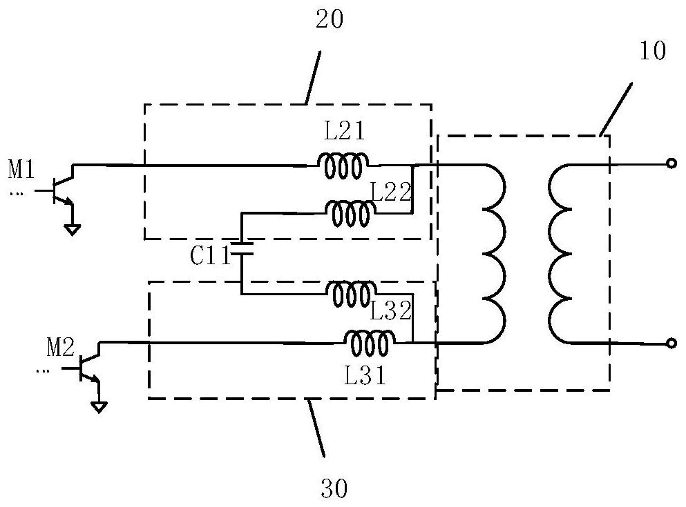
[0005] Embodiments of the present invention provide a push-pull power amplifier circuit and a radio frequency front-end module to solve the problem of large output loss of the push-pull power amplifier circuit

Method used


Image

  • Push-pull power amplification circuit and radio frequency front-end module
  • Push-pull power amplification circuit and radio frequency front-end module
  • Push-pull power amplification circuit and radio frequency front-end module

Examples


Embodiment Construction

[0030] The following will clearly and completely describe the technical solutions in the embodiments of the present invention with reference to the accompanying drawings in the embodiments of the present invention. Obviously, the described embodiments are some of the embodiments of the present invention, but not all of them. Based on the embodiments of the present invention, all other embodiments obtained by persons of ordinary skill in the art without creative efforts fall within the protection scope of the present invention.

[0031] It should be understood that the invention can be embodied in different forms and should not be construed as limited to the embodiments set forth herein. Rather, these embodiments are provided so that this disclosure will be thorough and complete, and will fully convey the scope of the invention to those skilled in the art. In the drawings, the size and relative sizes of layers and regions may be exaggerated for clarity, and like reference numer...


PUM


Abstract

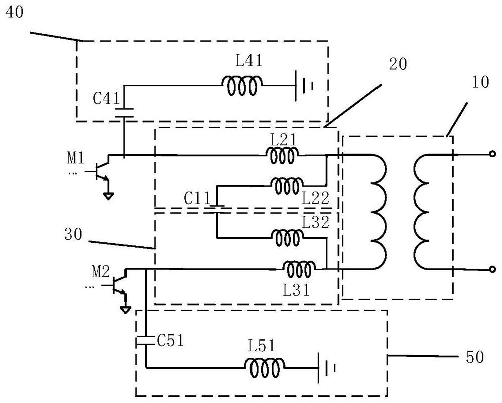
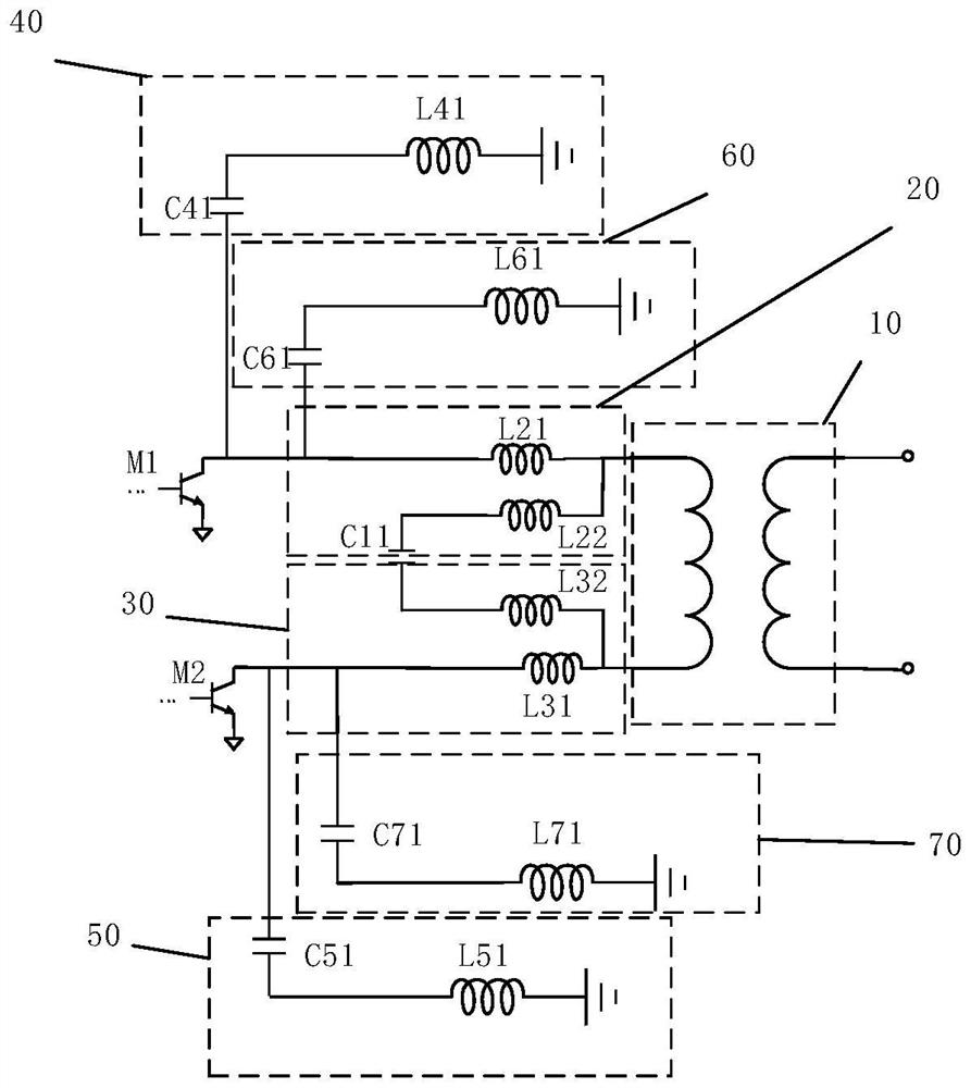
The invention discloses a push-pull power amplification circuit and a radio frequency front-end module. The push-pull power amplification circuit comprises a first power amplification tube, a second power amplification tube, a first conversion balun and a first capacitor; the first input end of the first conversion balun is connected with the output end of the first power amplification tube through a first inductor, and the first input end of the first conversion balun is connected with the first end of the first capacitor through a second inductor; the second input end of the first conversion balun is connected with the output end of the second power amplifier tube through a third inductor, and the second input end of the first conversion balun is connected with the second end of the first capacitor through a fourth inductor; therefore, the impedance conversion pressure of the first conversion balun for impedance conversion of the push-pull power amplification circuit is relieved, the first conversion balun can realize impedance conversion by adopting a small number of coil turns, and the output loss of the push-pull power amplification circuit is further reduced.

Description

technical field [0001] The invention relates to the technical field of radio frequency amplification, in particular to a push-pull power amplifier circuit and a radio frequency front-end module. Background technique [0002] The push-pull power amplifier circuit uses two transistors with the same characteristics to make them both work in the B state, one of the transistors works in the positive half cycle, and the other transistor works in the negative half cycle, and then the output waveforms of the two transistors are applied to the load Combined together, an amplifying circuit with a complete output waveform is obtained. [0003] The push-pull power amplifying circuit is generally connected to the post-stage load through the post-stage load balun, wherein the post-stage load balun is used to perform impedance conversion on the output impedance of the push-pull power amplifying circuit, that is, to convert the output impedance of the push-pull power amplifying circuit The...

Claims


Application Information

Patent Timeline
IPC IPC(8): H03F1/56H03F3/19H03F3/21H03F3/26
CPCH03F1/565H03F3/19H03F3/21H03F3/26H03F2200/451
Inventor 黄水根吕彬彬石宪青闵鸣张文达李想曹原倪建兴
Owner RUIPAN MICROELECTRONICS TECH (SHANGHAI) CO LTD
Learn More