Novel closed cooling tower adopting glass lining finned tube

A closed cooling tower, finned tube technology, applied in water shower coolers, heat exchanger types, direct contact heat exchangers, etc. Prolonged service life, good latent heat of evaporation, good heat exchange effect

Active Publication Date: 2022-02-15
HEBEI AIJIE PUMP TECH
View PDF8 Cites 0 Cited by
  • Summary
  • Abstract
  • Description
  • Claims
  • Application Information

AI Technical Summary

Problems solved by technology

[0006] The technical problem to be solved by the present invention is to provide a new type of closed cooling tower using glass-lined finned tubes, which is used to solve the problem that the filling of the cooling tower in the prior art is prone to clogging, thereby affecting the normal operation of the cooling tower

Method used


Image

  • Novel closed cooling tower adopting glass lining finned tube
  • Novel closed cooling tower adopting glass lining finned tube
  • Novel closed cooling tower adopting glass lining finned tube

Examples


Embodiment 1

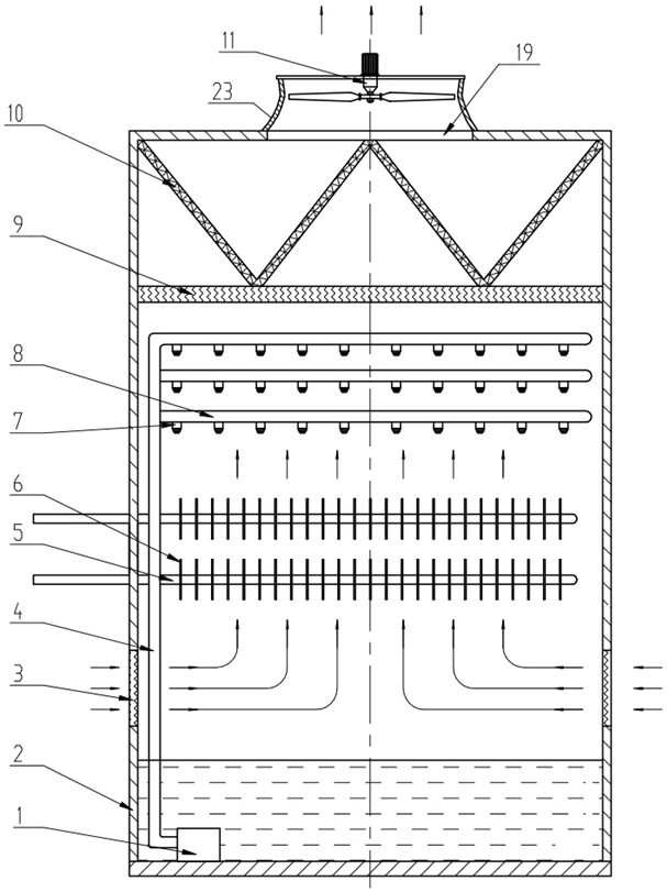
[0035] Such as figure 1 As shown, a new type of closed cooling tower adopting glass-lined finned tubes includes a rectangular box 2, and the inside of the box 2 is sequentially provided with a water storage layer, a heat exchange layer, and a water recovery layer for recycling water. The recycling layer for the fog. The water storage layer is located at the bottom of the box body 2, and water is stored inside it. The lower part of the heat exchange layer is provided with air inlets 3 on the walls of the four sides of the box body 2, and the air inlets 3 are all provided with louvers. The center of the top of the box body 2 is provided with an air outlet 19, and the outside of the box body 2 is welded with a shroud 23 at the air outlet 19, and the inside of the shroud is fixedly connected with a fan 11, and the type of the fan 11 is a shaft. streaming.

[0036] The water storage layer is arranged at the bottom of the box body 2, and the heat exchange layer includes a horizon...

Embodiment 2

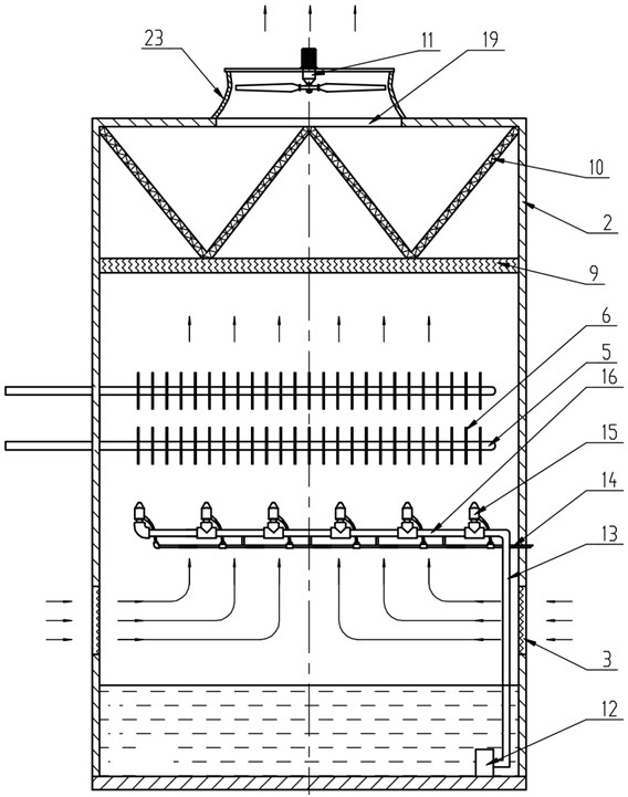
[0045] Such as figure 2 Shown, the difference between this embodiment and embodiment 1 is:

[0046] The spraying device is replaced with a spraying device, and the spraying device includes a horizontal spraying water pipe 16, a horizontal air supply pipe 14 arranged below the spraying water pipe 16, an atomizing nozzle 15 uniformly distributed along the spraying water pipe 16 and fixedly connected thereto And the vertical second water supply pipe 13 that connects the spray water pipe 16 with the water storage layer. The atomizing nozzles 15 are all upward toward the coil pipe 5, and the air inlets of the atomizing nozzles 15 are all connected to the air supply pipe 14, and the air supply pipe 14 passes through the side wall of the box body 2 to the right and is connected to the compressed air pipeline . The lower end of the second water supply pipe 13 is provided with a spray pump 12, the spray pump 12 is a submersible pump B installed in the water of the water storage laye...

Embodiment 3

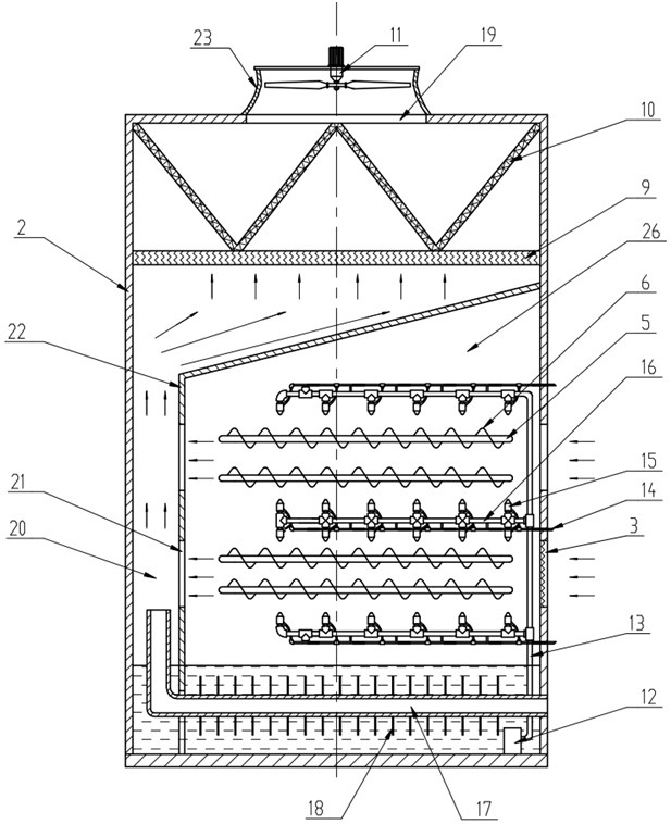
[0050] Such as image 3 As shown, the box body 2 is welded with a Γ-shaped partition 22 in the heat exchange layer, and the partition 22 is composed of a vertical vertical plate and a slant plate welded on the top of the vertical plate. The lower end of the vertical plate extends below the water surface of the water storage layer, and the partition plate 22 separates the heat exchange layer into a heat exchange chamber on the right and an air channel 20 on the left. The water storage layers on the left and right sides of the riser are connected at the bottom of the box body 2 . The vertical plate is provided with a middle hole 21, and the middle hole 21 connects the heat exchange chamber and the air duct 20 horizontally. The top of the air duct 20 communicates with the recovery layer, and the wind direction in the heat exchange chamber is horizontal.

[0051] The coiled pipe 5 has 4 layers in total, and two layers form a group. A spray water pipe 16 and an atomizing nozzle ...


PUM


Abstract

Disclosed is a novel closed cooling tower adopting a glass lining finned tube. The novel closed cooling tower comprises a box body, a water storage layer, a heat exchange layer and a recycling layer used for recycling water mist are sequentially arranged in the box body from bottom to top, an air inlet is formed in the position, corresponding to the lower portion of the heat exchange layer, of the box wall of the box body, an air outlet is formed in the top of the box body. A fan is fixedly arranged at the air outlet outside the box body; the water storage layer is arranged at the bottom of the box body, the heat exchange layer comprises a coil pipe and a spraying device used for spraying water to the coil pipe or the heat exchange layer comprises the coil pipe and a spraying device used for spraying mist to the coil pipe, the coil pipe is fixedly connected with the box body, and glass is enameled on the outer wall of the coil pipe. As the filler is not used any more, the problem that the normal operation of the cooling tower is influenced by filler blockage is avoided.

Description

technical field [0001] The invention relates to the technical field of heat exchange equipment, in particular to a novel closed cooling tower using glass-lined finned tubes. Background technique [0002] The cooling tower uses water as a circulating coolant, and uses water and air to exchange heat and cold to generate steam. The steam volatilizes and takes away the heat to achieve evaporation, convection heat transfer, and radiation heat transfer. Evaporative cooling device for waste heat generated. [0003] The usual cooling tower is equipped with fillers. Under the working condition of poor process environment, the filler plates are staggered with each other due to different angles, so the filler plates are easy to deposit sulfur paste and dirt, causing gas-liquid drift and forming filler dry areas. In severe cases, it will lead to blockage of the packing in the tower, which will affect the normal and stable operation of the cooling tower. [0004] The patent application...

Claims


Application Information

Patent Timeline
IPC IPC(8): F28C1/14F28C1/16F28F25/02F28F25/06F28F25/10
CPCF28C1/14F28C1/16F28F25/02F28F25/06F28F25/10
Inventor 马辉杨宏亮杜斌李晓鹏侯雄飞
Owner HEBEI AIJIE PUMP TECH
Why Eureka
Try Eureka