Aircraft test airflow organization design method

A technology of airflow organization and design method, which is applied in the field of aircraft test airflow organization design, can solve the problems of temperature field uniformity, difficult airflow organization design of large-scale climate environment laboratory, no design and construction experience, etc., and achieve the effect of accurate analysis

Active Publication Date: 2022-02-15
CHINA AIRPLANT STRENGTH RES INST
View PDF12 Cites 1 Cited by
  • Summary
  • Abstract
  • Description
  • Claims
  • Application Information

AI Technical Summary

Problems solved by technology

Due to the large volume of the laboratory, the number of air circulation in the cabin cannot reach hundreds of times per hour like a small environmental test box / chamber, which will inevitably have a greater impact on the uniformity of the temperature field
Traditional airflow organization design methods (such as jet flow formula method, Zonal Model model, experimental method, etc.) are difficult to directly apply to the airflow organization design of large-scale climate and environmental laboratories, and there is no relevant design and construction experience in China

Method used


Image

  • Aircraft test airflow organization design method
  • Aircraft test airflow organization design method
  • Aircraft test airflow organization design method

Examples


Embodiment

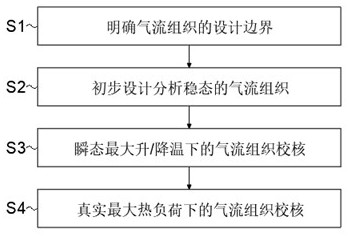
[0092] In order to achieve the above objectives, the present invention provides a design method for aircraft test airflow organization, which satisfies the design requirements of setting a high uniformity temperature field in an extreme climate environment in a super large space, and is relevant for the design of an air handling system for aircraft testing And the laboratory layout provides technical support, the specific steps are as follows:

[0093] S1. Clarify the design boundary of airflow organization: clarify the functional requirements of the laboratory, the constraints on airflow organization, and the layout restrictions of building structures;

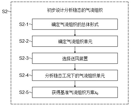
[0094] S2. Preliminary design analysis of steady-state airflow organization:

[0095] S2-1. Determine the overall form of the airflow organization: based on the constraint conditions in step S1, determine the overall form of the airflow organization as upward feeding and downward return;

[0096] S2-2. Determine the airflow ...

Embodiment 2

[0159] The difference between this embodiment and embodiment 1 is:

[0160] In step S2-2, the aspect ratio of the airflow organization unit is 1:1.2;

[0161] In step S2-3, the air supply device is preferably a swirl tuyere, and the air supply tangential angle of the swirl tuyere is 90°;

[0162] The number of the fan-shaped areas is 20.

Embodiment 3

[0164] The difference between this embodiment and embodiment 1 is:

[0165] In step S2-2, the aspect ratio of the airflow organization unit is 1:1.1;

[0166] In step S2-3, the air supply device is preferably a swirl tuyere, and the air supply tangential angle of the swirl tuyere is 60°;

[0167] The number of the fan-shaped areas is 16.


PUM


Abstract

The invention relates to the technical field of aircraft testing, in particular to an aircraft test airflow organization design method. The purpose of designing a high-uniformity temperature field in an extreme climate environment in an ultra-large space is achieved through a method comprising the steps of defining a design boundary of an air flow structure, preliminarily designing and analyzing the steady-state air flow structure, checking the air flow structure under transient maximum heating/cooling and checking the air flow structure under real maximum thermal load. Technical support is provided for design of related air treatment systems and laboratory layout; according to the design method provided by the invention, the design of the airflow structure with high uniformity and low wind speed field is completed by stages, and the comprehensive analysis and design of the airflow structure can be completed in a short time; in addition, ground convective heat transfer coefficients under factors such as different air supply flows and air supply temperature differences are considered and serve as input parameters of ground temperature response analysis, and airflow organization can be analyzed and checked more accurately.

Description

technical field [0001] The invention relates to the technical field of aircraft testing, in particular to an airflow organization design method for aircraft testing. Background technique [0002] The large-scale climate laboratory can simulate comprehensive climate environments such as extreme low temperature, high temperature, heat and humidity, snowfall, freezing rain, solar radiation, and rain to meet the comprehensive testing needs of large-scale equipment, especially aircraft. No country with a volume exceeding 100,000 m 3 The largest climate and environment laboratory in the world, only the McKinley Laboratory in the United States has a volume close to 100,000 m 3 , South Korea ADD laboratory is 20000 m 3 about. [0003] The main simulation room of the McKinley Climate Laboratory is the largest adiabatic simulation room in the world. Its airflow organization adopts the way of sending upwards and returning downwards. There are four air ducts suspended on the top of t...

Claims


Application Information

Patent Timeline
Patent Type & Authority Applications(China)
IPC IPC(8): G06F30/28G06F30/20G06F111/04G06F113/08G06F119/08G06F119/14
CPCG06F30/28G06F30/20G06F2113/08G06F2119/14G06F2119/08G06F2111/04
Inventor 王彬文成竹吴敬涛马建军任战鹏
Owner CHINA AIRPLANT STRENGTH RES INST
Why Eureka
Try Eureka