A compound hybrid excitation multi-degree-of-freedom spherical motor
A hybrid excitation and spherical motor technology, applied to synchronous motors with stationary armatures and rotating magnets, magnetic circuits, electromechanical devices, etc., can solve the torque performance and range of motion limitations of multi-degree-of-freedom motors To solve problems such as serious road coupling and poor motor output performance, it achieves the effects of easy analysis and control, low coupling degree, and large deflection angle
- Summary
- Abstract
- Description
- Claims
- Application Information
AI Technical Summary
Problems solved by technology
Method used
Image
Examples
Embodiment 1
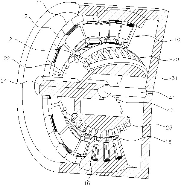
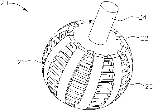
[0040] refer to Figure 1 to Figure 4 , showing a compound hybrid excitation multi-degree-of-freedom spherical motor, including a stator 10 and a rotor 20, the stator 10 and the rotor 20 are installed with reference to the same spherical center, and the gap between the stator 10 and the rotor 20 forms a spherical air gap, that is, the stator 10 The surface on the air gap side and the surface on the air gap side of the rotor 20 are both concentric equivalent spherical arc structures, and there is a regular and uniform air gap between the two surfaces.
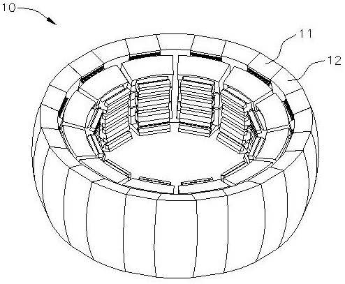
[0041] like figure 2 , the stator 10 includes a plurality of stator core units 11, and a stator connection core 12 is arranged between two adjacent stator core units 11. combine Figure 4 The stator core unit 11 is provided with at least three stator teeth 13, the three stator teeth 13 are wound with windings 16, and the stator teeth 13 are provided with stator permanent magnets 15. The yoke of the stator core unit 11 and th...
Embodiment 2
[0071] refer to Figure 10 , the compound hybrid excitation multi-degree-of-freedom spherical motor of this embodiment is different from the first embodiment in that it adopts an inner stator and outer rotor structure. Specifically, the housing 31 is connected and fixed to the stator 10 , and the rotor center shaft 24 of the rotor 20 and the bearing strut 41 are connected spherically through the bearing lubricating spherical surface 42 . In the stator 10, the stator permanent magnets 15 on the stator teeth 13 are arranged radially outward, and the magnetization directions of the stator permanent magnets 15 are radially outward; in the rotor 20, the rotor grooves are arranged radially inward, facing the stator. 10 Surfaces on the air gap side. The bearing lubricating spherical surface 42 in this embodiment is provided on the end of the rotor center shaft 24 .
[0072] In the above two embodiments, the rotor permanent magnets 21 are installed in the rotor 20 in a surface-mount...
PUM
 Abstract
Description
Claims
Application Information
 - R&D
- Intellectual Property
- Life Sciences
- Materials
- Tech Scout
- Unparalleled Data Quality
- Higher Quality Content
- 60% Fewer Hallucinations
Browse by: Latest US Patents, China's latest patents, Technical Efficacy Thesaurus, Application Domain, Technology Topic, Popular Technical Reports.
© 2025 PatSnap. All rights reserved.Legal|Privacy policy|Modern Slavery Act Transparency Statement|Sitemap|About US| Contact US: help@patsnap.com


