Novel wafer surface drying device

A surface drying and wafer technology, applied in drying, drying machines, heating devices, etc., can solve the problems that the actual yield rate of wafers cannot be effectively counted, and the quality data is difficult to obtain statistics and other problems

Active Publication Date: 2022-02-22
NANTONG MINICHIP MICRO ELECTRONICS
View PDF7 Cites 0 Cited by
  • Summary
  • Abstract
  • Description
  • Claims
  • Application Information

AI Technical Summary

Problems solved by technology

The utility model can realize rapid and uniform drying treatment of multiple groups of wafers, has good drying effect, does not occupy a large amount of ground space, has high drying efficiency, saves time and effort, and improves work efficiency." The drying device is performing wafer drying During dry processing, it is impossible to effectively count the actual yield rate of the wafer, and it is difficult to obtain statistical data on the quality of the wafer after drying;

Method used


Image

  • Novel wafer surface drying device
  • Novel wafer surface drying device
  • Novel wafer surface drying device

Examples


Embodiment 1

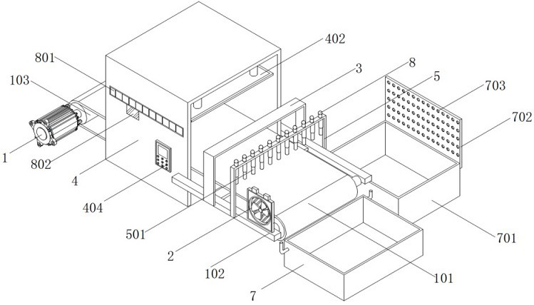
[0045] see Figure 1-Figure 3 , an embodiment provided by the present invention: a novel wafer surface drying device, comprising a drying frame 4 and a conveying fan 2, a crosspiece 102 is installed on the front and back of the drying frame 4, and the top of the front crosspiece 102 A delivery fan 2 is installed, and the delivery fan 2 is located on one side of the marking frame 5;

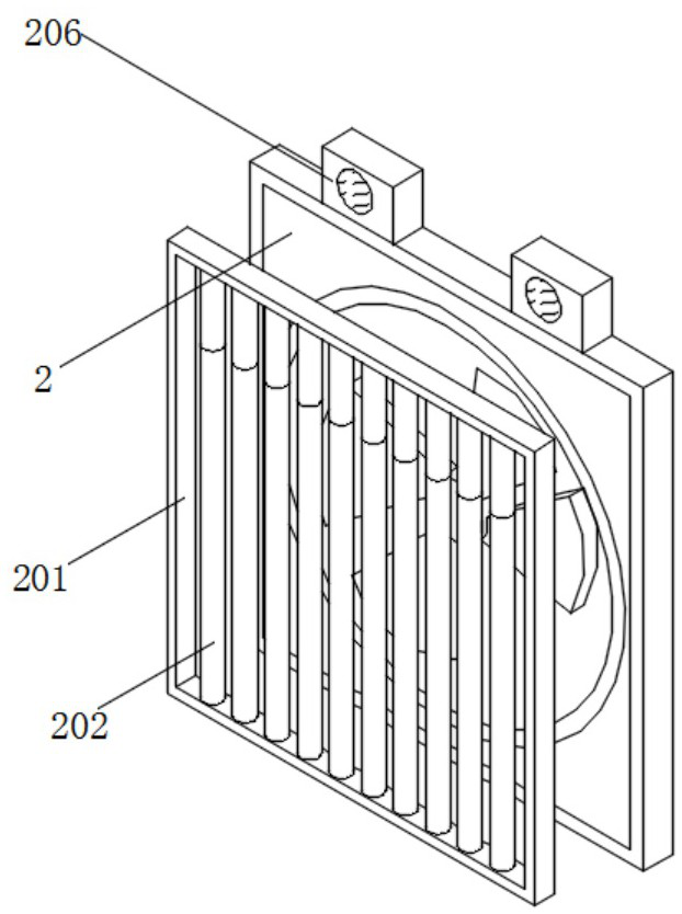
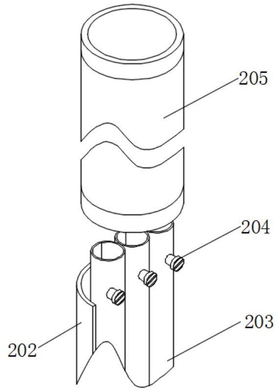
[0046] A connecting frame 201 is installed on the back of the conveying fan 2, an infrared thermometer 206 is installed on the top of the conveying fan 2, a hollow metal pipe 202 is installed on the bottom wall of the connecting frame 201, and three sets of equidistant air ducts are installed inside the metal pipe 202 203, an electronic valve 204 is installed on the surface of the air duct 203, the electronic valve 204 is electrically connected to the infrared thermometer 206, the top of the air duct 203 is fitted with a liquid nitrogen tube 205, and the top of the liquid nitrogen tube 205 is conn...

Embodiment 2

[0051] see Figure 5 , an embodiment provided by the present invention: a novel wafer surface drying device, comprising a drying frame 4, a No. 2 infrared heating plate 403 is installed on the inner wall of the drying frame 4, and the four corners of the top wall of the drying frame 4 are An electric telescopic cylinder 401 is installed, and the bottom of the electric telescopic cylinder 401 is connected with a No. 1 infrared heating plate 402, and a temperature controller 404 is installed on the front of the drying frame 4, and a control button and a temperature detector are installed on the surface of the temperature controller 404, and The temperature detector is located above the control button. The temperature detector is electrically connected to the No. 1 infrared heating plate 402 and the No. 2 infrared heating plate 403 . The No. 2 infrared heating plate 403 is located in the middle of the conveyor belt 101 .

[0052] Specifically, start the electric telescopic tube 4...

Embodiment 3

[0055] see figure 1 , an embodiment provided by the present invention: a novel wafer surface drying device, including a counter 8, a counter 8 equidistantly arranged on the top of the marking frame 5, and a No. 1 display screen 801 installed on the front of the drying frame 4 , the installation quantity of No. 1 display screen 801 is equal to the installation quantity of counter 8, No. 2 display screen 802 is installed on the front of drying frame 4, and No. 2 display screen 802 is positioned at the bottom of No. 1 display screen 801, and No. 2 display The screen 802 is electrically connected to the No. 1 display screen 801 , and the No. 1 display screen 801 is electrically connected to the counter 8 one by one. The No. 2 display screen 802 is located above the temperature controller 404 .

[0056] Specifically, since the wafers placed on the surface of the conveyor belt 101 are arranged in columns, the production batches of the wafers discharged in each column may be differen...


PUM


Abstract

The invention discloses a novel wafer surface drying device which comprises a drying frame, crosspieces are installed on the front face and the back face of the drying frame, a detection frame and a marking frame are installed on the surfaces, away from each other, of the two crosspieces, and a conveying fan is installed at the top of the crosspiece in the front; a connecting frame is installed on the back face of the conveying fan, an infrared thermometer is installed on the top of the conveying fan, a hollow metal pipe is installed on the bottom wall of the connecting frame, three sets of air guide pipes arranged at equal intervals are installed in the metal pipe, and an electronic valve is electrically connected with the infrared thermometer. A liquid nitrogen pipe is connected to the top of the gas guide pipe in an embedded mode. According to the device, the conveying fan and the marking frame are arranged, whether the surface of the wafer has the swelling phenomenon or not can be detected through an ultrasonic range finder at the bottom of the marking frame, the swelling wafer is marked through an electric telescopic rod, an electric push rod and a marking plate, then screening and classification are conducted through the conveying fan, and good products and defective products are distinguished.

Description

technical field [0001] The invention relates to the technical field of wafer drying, in particular to a novel wafer surface drying device. Background technique [0002] Wafer refers to the silicon wafer used in the production of silicon semiconductor integrated circuits. Because of its round appearance after production, it is also called wafer. The raw material of wafer is silicon. The difference from silicon wafer is that wafer The surface of the silicon wafer contains integrated circuits, but there is no integrated circuit on the surface of the silicon wafer. After the wafer is produced, it needs to be dried to remove the etching liquid on the surface, so as to protect the normal use of the wafer. [0003] The defect that existing wafer drying device exists is: [0004] 1. The comparative document CN205843288U discloses a wafer dryer, "comprising a frame and a drying chamber on the frame, a hot air supply device is provided above the drying chamber for Conveying hot air,...

Claims


Application Information

Patent Timeline
Patent Type & Authority Applications(China)
IPC IPC(8): F26B15/18F26B21/10F26B23/04F26B3/30F26B25/02F26B25/06F25D3/10
CPCF26B15/18F26B21/001F26B21/004F26B21/10F26B23/04F26B3/30F26B25/02F26B25/06F25D3/10
Inventor 周明
Owner NANTONG MINICHIP MICRO ELECTRONICS
Why Eureka
Try Eureka