An integrated painting and spraying volatile organic waste gas treatment equipment
A waste gas treatment equipment and volatile organic waste gas technology, which is applied in the field of integrated painting and spraying volatile organic waste gas treatment equipment, can solve the problems of reduced operating efficiency and easy pollution of the adsorption medium by paint mist, so as to reduce operating costs and improve adsorption Efficiency and service life, the effect of meeting processing needs
- Summary
- Abstract
- Description
- Claims
- Application Information
AI Technical Summary
Problems solved by technology
Method used
Image
Examples
Embodiment 1
[0037] According to an embodiment of the present invention,
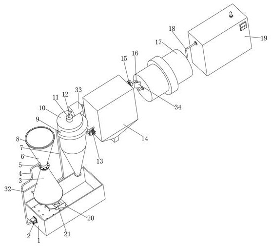
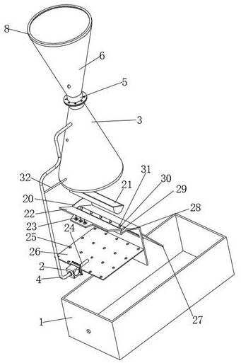
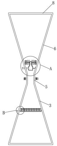
[0038] see Figure 1-Figure 8 , an integrated painting and spraying volatile organic waste gas treatment equipment, including a venturi tube dust collector 8, a cyclone dust collector 10 is arranged on one side of the venturi tube dust collector 8, and a row is inserted on the top outer wall of the cyclone dust collector 10 The air pipe 11, the top of the exhaust pipe 11 is plugged with a second air guide pipe 12, one side of the cyclone dust collector 10 is provided with a first dehumidifier 33, and the end of the second air guide pipe 12 away from the cyclone dust collector 10 is plugged with a second air guide pipe 12. A fan 13, one end of the first fan 13 is provided with a bag filter 14, the first dehumidifier 33 communicates with the cyclone dust collector 10 and the bag filter 14 through the second air duct 12, and the bag filter 14 is far away from the cyclone One end of the dust remover 10 is provided with...
Embodiment 2
[0040] see Figure 1-Figure 2 A water storage tank 1 is arranged below the venturi dust collector 8, and a pump body 2 is fixedly connected to one side outer wall of the water storage tank 1, and a catheter tube 4 is inserted into one side outer wall of the pump body 2, and one end of the catheter tube 4 Extending to the inside of the venturi dust collector 8, the catheter 4 communicates with the atomization assembly, the bottom outer wall of the venturi dust collector 8 is fixedly connected with a fixed column 23, and the bottom end of the fixed column 23 is fixedly connected with a deflector 22 , one end of the deflector 22 away from the fixed column 23 is fixedly connected to the bottom inner wall of the water storage tank 1, and one side of the outer wall of the deflector 22 is fixedly connected to a slant plate 27, and the bottom end of the swash plate 27 is connected to the bottom inner wall of the water storage tank 1. No contact, the outer walls on both sides of the de...
Embodiment 3
[0044] see figure 1 , the outer peripheral wall of the Venturi tube dust collector 8 is plugged with a first air guide pipe 7, and the outer peripheral wall of the cyclone dust collector 10 is fixedly connected with a guide tube 9, and the guide tube 9 communicates with the cyclone dust collector 10, and the guide tube 9 The inner diameter of the first air duct 7 gradually becomes smaller from left to right, and the end of the first air duct 7 away from the venturi dust collector 8 is plugged into the inside of the duct 9. Since the duct 9 is connected to the cyclone dust collector 10, and the diversion The inner diameter of the pipe 9 gradually decreases from left to right, so that the waste gas entering the cyclone 10 can have a certain initial velocity, thereby further improving the treatment effect of the cyclone 10 on the waste gas.
PUM
 Abstract
Description
Claims
Application Information
 - R&D
- Intellectual Property
- Life Sciences
- Materials
- Tech Scout
- Unparalleled Data Quality
- Higher Quality Content
- 60% Fewer Hallucinations
Browse by: Latest US Patents, China's latest patents, Technical Efficacy Thesaurus, Application Domain, Technology Topic, Popular Technical Reports.
© 2025 PatSnap. All rights reserved.Legal|Privacy policy|Modern Slavery Act Transparency Statement|Sitemap|About US| Contact US: help@patsnap.com


