Drug treatment device for anesthesiology department
A processing device and an anesthesiology technology, applied in chemical/physical processes, mixers with rotating stirring devices, transportation and packaging, etc., can solve the problems of unprocessable conditions and output condition analysis, use effects that need to be improved, and inconvenient use and other problems, to achieve the effect of saving time and effort in the processing process, improving the use effect and improving the mixing effect
- Summary
- Abstract
- Description
- Claims
- Application Information
AI Technical Summary
Problems solved by technology
Method used
Image
Examples
Embodiment 1
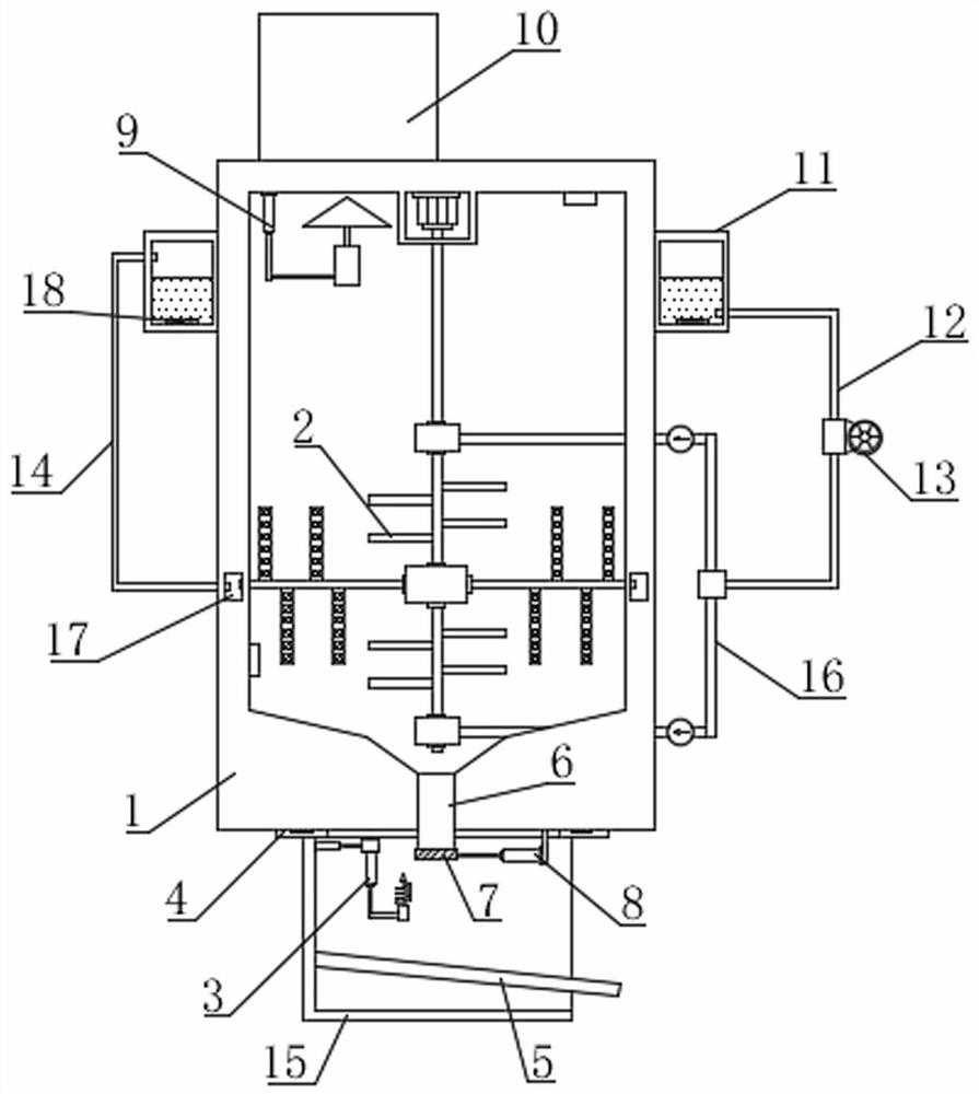
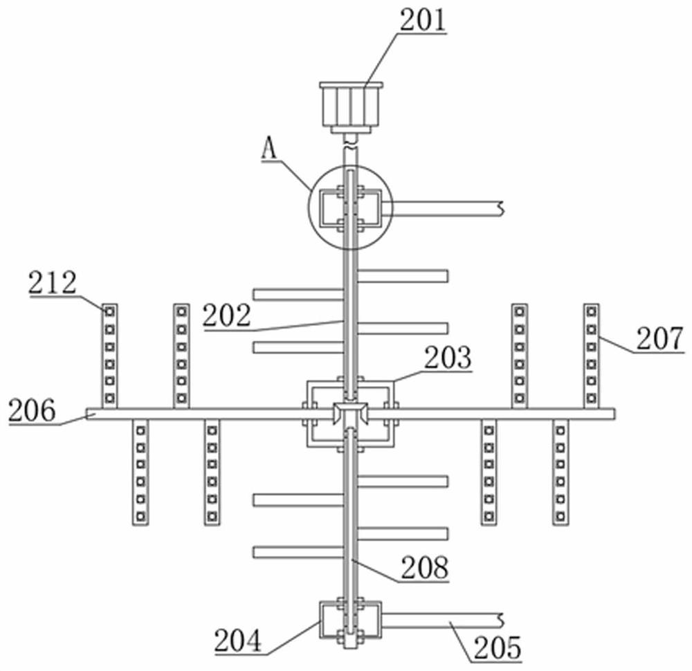
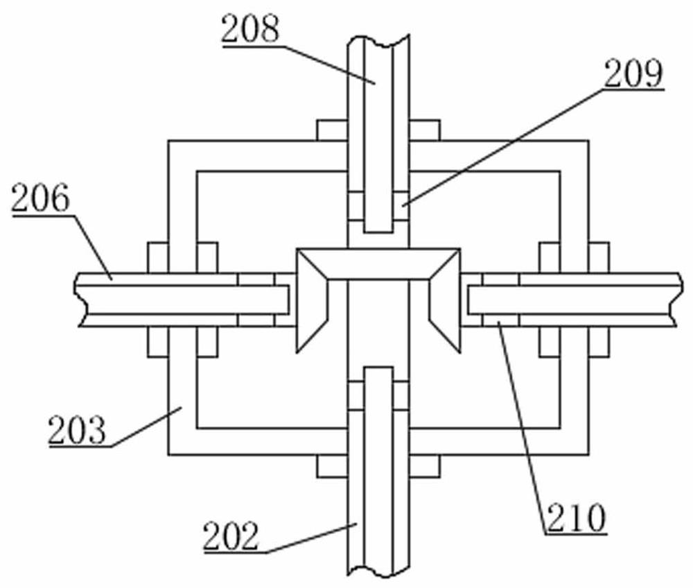
[0054] Such as Figure 1-10 As shown, a kind of anesthesia drug treatment device proposed by the present invention comprises a treatment box 1, the top of the treatment box 1 is fixed with a feed box 10 by bolts, a temperature sensor and a humidity sensor are arranged in the treatment box 1, and the temperature sensor It is used to collect the temperature of the material in the processing box 1, and the humidity sensor is used to collect the air humidity in the processing box 1. The heat conduction stirring component 2 is installed in the processing box 1. The semi-sealed box 15 is located below the treatment box 1. The semi-sealed box 15 is connected with the processing box 1 through the pressure-bearing plate 4, and a load cell is installed on the pressure-bearing plate 4, and the load cell is used for real-time detection of the pressure on the pressure-bearing plate 4 by the processing box 1; the bottom of the processing box 1 is opened There is a discharge pipeline 6 commu...
Embodiment 2
[0063] Such as figure 1 and Figure 11 As shown, the difference between this embodiment and Embodiment 1 is that an annular liquid storage tank 11 is installed on the outer wall of the processing box 1, and an electric heating plate 18 is installed in the annular liquid storage tank 11, and the electric heating plate 18 converts electric energy into heat energy to Heat the thermal fluid in the annular liquid storage tank 11, and the end of the liquid return pipe 14 away from the annular liquid return chamber 17 communicates with the annular liquid storage tank 11, and the annular liquid storage tank 11 is fixedly installed with an infusion tube 12, and the infusion tube 12 One end away from the annular liquid storage tank 11 is provided with a liquid distribution pipe 16, and an infusion pump 13 is provided on the infusion pipe 12. The liquid distribution pipe 16 is connected to two groups of liquid inlet pipes 205. When in use, start the infusion pump 13, and the infusion pum...
Embodiment 3
[0065] Such as figure 1 , Figure 14-15 As shown, the difference between this embodiment and Embodiment 1 and Embodiment 2 is that the pressure measurement guide material assembly 5 includes a material guide plate 51, and the material guide plate 51 is obliquely arranged in the semi-sealed box 15, and the upper part of the material guide plate 51 There is a groove 54, the pressure measuring plate 52 is arranged obliquely and pressed down into the groove 54, the number of the second spring 53 is multiple groups, the second spring 53 is arranged in the groove 54 and connects the material guide plate 51 and the pressure measuring plate 52, and a pressure measuring sensor is also provided in the groove 54. When in use, the material falling through the discharge pipe 6 falls on the pressure measuring plate 52, and the pressure measuring sensor detects the pressure on the pressure measuring plate 52. The second spring 53 buffers the falling impact force, and the material guide plat...
PUM
 Abstract
Description
Claims
Application Information
 - R&D
- Intellectual Property
- Life Sciences
- Materials
- Tech Scout
- Unparalleled Data Quality
- Higher Quality Content
- 60% Fewer Hallucinations
Browse by: Latest US Patents, China's latest patents, Technical Efficacy Thesaurus, Application Domain, Technology Topic, Popular Technical Reports.
© 2025 PatSnap. All rights reserved.Legal|Privacy policy|Modern Slavery Act Transparency Statement|Sitemap|About US| Contact US: help@patsnap.com


